
Introduction
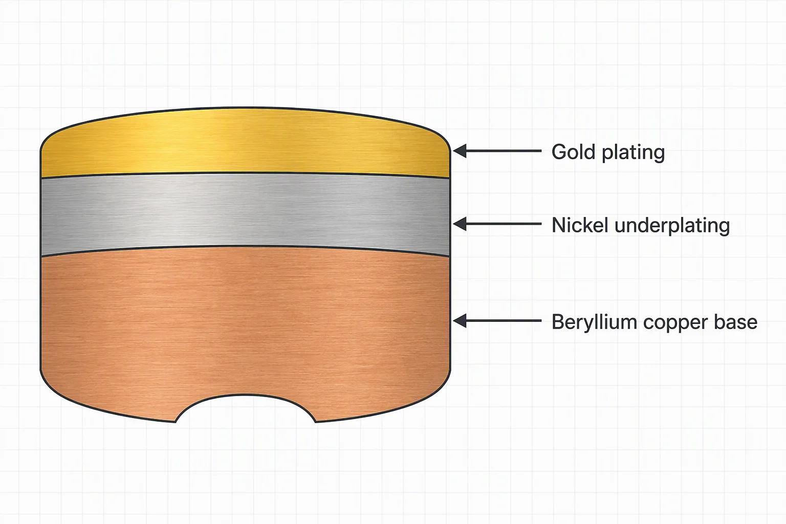
Gold-plated beryllium copper with nickel underplating is a multilayer material system used when a component needs a combination of spring performance, electrical functionality, surface durability, and controlled contact behavior. The structure normally consists of a beryllium copper base, a nickel underplating or barrier layer, and an electrodeposited gold surface.
This wording matters because the component does not consist entirely of gold. Gold forms the outer functional coating, nickel sits between the layers, and beryllium copper provides the mechanical and electrical base. Since each layer performs a different job, engineers should select the material by reviewing the complete stack rather than the word “gold” alone.
Engineers commonly consider this material system for electrical contacts, connector elements, spring contacts, terminals, probe components, switches, and other precision parts. However, actual suitability depends on contact force, mating cycles, current, voltage, environment, geometry, plating thickness, surface preparation, and the applicable product specification.
For related manufacturing context, see HengSheng Spring’s custom spring manufacturing, custom battery spring, and CNC wire forming capabilities.
What Is Gold-Plated Beryllium Copper?
Gold-plated beryllium copper is a beryllium-copper component finished with a nickel underplating and a gold surface layer. A clear technical description is:
Material: Beryllium copper with nickel underplating and gold-plated surface.
The three-layer structure follows a clear functional sequence:
- Beryllium copper base: It provides the component’s mechanical structure, spring behavior, and a useful balance of strength and conductivity.
- Nickel underplating: It acts as an intermediate layer that can improve barrier behavior, surface stability, and plating-system consistency.
- Gold plating: It provides the exposed contact surface. Its performance depends on coating type, thickness, hardness, porosity, surface finish, and the intended mating environment.
Do not guess the alloy grade from the general term “beryllium copper.” Common engineering grades use different copper-beryllium compositions and tempers, so strength, conductivity, forming behavior, and heat-treatment condition can vary. Therefore, the drawing or purchasing specification must identify the required alloy, temper, and applicable standard.
Why Use Beryllium Copper as the Base Material?
Spring performance and elastic recovery
Many engineers select beryllium copper for contact and spring components because the alloy can combine high mechanical strength with useful electrical and thermal conductivity. As a result, it suits parts that must deflect during assembly or mating and then return toward their original position.
Spring performance does not depend on the alloy name alone. Instead, it also depends on:
- Alloy grade and temper.
- Strip or wire thickness.
- Forming radius and residual stress.
- Heat-treatment condition.
- Contact geometry.
- Deflection amplitude and working stress.
- Temperature and environment.
For this reason, an engineer should specify the required force, deflection, stress range, and cycle expectation instead of requesting “beryllium copper” without a temper or geometry.
Conductivity with mechanical strength
Compared with many high-strength ferrous spring materials, copper-beryllium alloys can offer a useful combination of electrical conductivity and strength for compact contact components. However, conductivity varies between alloy families and tempers. Confirm it from the selected material datasheet or certificate rather than inferring it from the coating description.
The gold and nickel layers also influence the electrical interface. The resistance of a finished contact depends on the complete current path, including bulk resistance, constriction resistance, surface condition, contact force, contamination, and the mating material.
Formability and precision manufacturing
Manufacturers can produce beryllium copper in strip, wire, sheet, and other forms for stamping, forming, and precision contact production. They still need to control bend radius, burrs, edge condition, springback, cleanliness, and heat treatment.
A small plated contact can fail because a forming crack, damaged edge, poor cleaning, or incomplete plating coverage affects it—not because the nominal alloy was incorrect. Therefore, engineers should review material selection and process control together.
The Role of the Nickel Underplating
Nickel is not the exposed contact surface in this material stack. It is an intermediate layer between the beryllium copper base and the gold coating.
Barrier function
A nickel underplating can act as a barrier between the copper-based substrate and the gold surface. In turn, this barrier can help control interaction between the base metal and the outer coating during processing and service. The exact performance depends on plating chemistry, layer structure, thickness, porosity, adhesion, heat exposure, and product geometry.
Surface preparation and adhesion
The nickel layer delivers consistent results only when the complete plating process is properly controlled. Cleaning, activation, strike layers where applicable, current density, bath control, rinsing, drying, and handling all affect adhesion and surface quality.
If the supplier prepares the base material poorly, a visually bright gold surface may still show poor adhesion or unacceptable porosity. Therefore, engineers should ask for process controls and test methods, not only a color description.
Electrical and mechanical trade-offs
Nickel can have different electrical, hardness, and friction characteristics from gold and beryllium copper. A thicker or harder intermediate layer may alter forming behavior, contact compliance, or the effective interface if the gold coating is worn through.
The correct nickel specification depends on the application. The drawing must define whether the nickel layer acts as a barrier, forms a functional part of the contact system, or serves as a controlled undercoat. It must also state the measurement method and acceptable range when thickness is critical.
Why Gold Is Used as the Surface Layer
Many engineers choose gold for contact surfaces because it provides a stable noble-metal interface and can support consistent low-level contact behavior when the plating system is correctly designed. However, every gold-plated part still requires application-specific validation.
Important variables include:
- Gold purity and deposit type.
- Hard or soft gold selection.
- Surface roughness and finish.
- Plating thickness.
- Porosity and pinhole control.
- Underplating structure.
- Contact force and wiping action.
- Mating material and contact geometry.
- Environmental exposure.
ASTM B488 provides a public engineering reference for electrodeposited gold coatings in engineering applications. Use it alongside the actual drawing, application requirement, and purchaser-supplier agreement. However, a general coating standard does not automatically define the correct thickness, hardness, or performance for every connector or spring contact.
Gold plating is also not a substitute for mechanical design. If the contact force is too low, the mating geometry is unstable, or particles accumulate at the interface, the finished part may not meet its electrical or reliability target even when the gold layer looks acceptable.
Typical Applications
Electrical connectors and terminals
Engineers often consider gold-plated beryllium copper for connector terminals and contact springs that require repeatable mating behavior in a compact form. Before approval, the design team must evaluate insertion force, normal force, wipe length, mating cycles, current level, temperature, and contamination.
Probe contacts and test fixtures
Test probes and fixture contacts may benefit from a spring base combined with a controlled surface finish. Here, contact tip geometry and replacement interval can matter as much as the plating specification.
Switches and low-level signal contacts
Low-level signal interfaces are sensitive to surface films, contamination, contact force, and mechanical stability. Engineers may select gold-plated surfaces for a stable interface, but the design team must still define switching action, current range, voltage, environmental exposure, and expected life.
Battery, sensor, and electronic assemblies
Designers may use plated copper alloys for compact spring contacts and terminals when space, spring force, and electrical connection must work together. Meanwhile, battery and sensor applications demand careful review of vibration, temperature, corrosion exposure, mating compatibility, and assembly damage.
Precision spring components
A beryllium copper spring can provide the mechanical function while the plating system controls the exposed surface. Before approval, the manufacturer must verify that forming, heat treatment, cleaning, and plating preserve the required spring properties and avoid cracking at bends and edges.

Manufacturing Process Overview
The exact sequence varies by supplier and component, but a typical process may include the following stages.
1. Material selection and incoming inspection
The manufacturer verifies the alloy, temper, thickness, hardness, surface condition, and certificate information. ASTM B194 is one public reference for copper-beryllium plate, sheet, strip, and rolled bar; the applicable material standard depends on the product form and project requirements.
2. Stamping, forming, or machining
The manufacturer shapes the base component to the approved drawing. Critical controls include dimensional accuracy, bend radius, burr height, springback, edge cracks, and deformation after forming.
3. Stress relief or heat treatment where specified
Some beryllium copper components require a controlled heat-treatment condition to achieve their specified mechanical properties. The manufacturer must coordinate that process with the planned plating sequence and the component’s final dimensional tolerances.
4. Cleaning and surface preparation
Oil, oxides, fingerprints, forming residues, and other contamination can compromise adhesion. The supplier must validate cleaning and activation for the specific alloy, geometry, and plating line.
5. Nickel underplating
The plating line deposits the nickel layer under controlled bath and current conditions. The process must maintain consistent coverage on edges, internal features, contact faces, and recessed areas that affect final function.
6. Gold plating
The plating line applies the gold deposit over the nickel-prepared surface. The supplier must control deposit appearance, thickness, hardness where relevant, coverage, adhesion, porosity, and contamination.
7. Inspection and functional testing
Final inspection can include dimensional checks, visual inspection, coating-thickness measurement, adhesion testing, hardness or material verification, contact-resistance testing, and simulated mating or environmental testing. Engineers should link the test plan to the actual application risk.
Engineering and Procurement Specification Checklist
A purchase request must do more than say “gold-plated beryllium copper.” It must define the complete material and performance requirement.
Base material
- Copper-beryllium alloy designation.
- Material standard and product form.
- Temper or heat-treatment condition.
- Thickness, wire diameter, or starting stock size.
- Required tensile, hardness, spring-force, or conductivity range.
- Restrictions on substitutes.
Nickel underplating
- Nickel type or process family where relevant.
- Minimum, nominal, and maximum thickness if critical.
- Coverage requirements for edges, holes, bends, and contact faces.
- Adhesion and porosity requirements.
- Measurement method and sampling plan.
Gold surface
- Gold deposit type and applicable engineering coating standard.
- Minimum or nominal thickness.
- Hardness requirement for sliding or repeated mating.
- Appearance and surface-finish requirement.
- Contact-resistance or environmental performance requirement.
- Areas that must remain unplated or require selective plating.
Part geometry and performance
- Contact force and deflection.
- Mating cycle or insertion requirement.
- Current and voltage range.
- Operating temperature.
- Vibration, humidity, salt, chemical, or industrial atmosphere exposure.
- Packaging and handling controls.
Quality documentation
- Material certificates.
- Plating-process records.
- Coating-thickness results.
- Adhesion or porosity test results where required.
- Dimensional inspection report.
- Functional contact-resistance data where specified.
- Change-control and traceability requirements.
Common Selection Mistakes
Mistake 1: Treating “gold-plated” as a complete specification
Gold color does not identify the base alloy, coating thickness, hardness, barrier structure, or electrical performance. State the complete material stack explicitly.
Mistake 2: Omitting the beryllium-copper temper
Two components from the same general alloy family can behave differently when their tempers, thicknesses, or heat treatments differ. Define the material condition before setting spring-force and fatigue expectations.
Mistake 3: Ignoring the nickel layer
The nickel underplating can influence adhesion, diffusion behavior, forming response, friction, and the result after surface wear. Treat it as a controlled process layer, not as an invisible detail.
Mistake 4: Specifying thickness without a test method
A number without a measurement method can produce disputes between buyer and supplier. Identify the test method, sampling location, calibration expectations, and acceptance criteria in the specification.
Mistake 5: Using the same plating design for every environment
A low-level indoor signal contact, a repeated-wipe connector, and an outdoor industrial terminal may require different coating structures and validation tests. Let the environment and contact mechanics guide the plating decision.
Mistake 6: Overlooking beryllium exposure controls
Beryllium-containing materials require appropriate industrial hygiene and process controls, particularly during operations that can generate dust or fumes. During machining, grinding, polishing, and heat-related operations, follow applicable occupational-safety requirements and the supplier’s approved process controls.
Design and Reliability Considerations
Contact resistance is a system property
Bulk material resistivity explains only part of the final contact resistance. The complete result also includes contact geometry, normal force, real area of contact, surface roughness, contamination, oxide or film formation, plating integrity, and movement between mating surfaces.
Therefore, verify the coating decision with the actual contact design and a representative test fixture. A flat coupon test may not predict how a small stamped spring contact behaves under vibration or repeated mating.
Plating thickness is a design variable
A thicker coating is not automatically better. Increasing thickness can affect cost, dimensional fit, edge buildup, forming behavior, and friction. Link the required thickness to the wear mechanism, expected life, environment, and applicable coating specification.
Selective plating can reduce cost and control performance
Some components need gold only on the contact zone. Selective plating can reduce precious-metal consumption and keep other areas available for soldering, welding, crimping, or mechanical retention. The transition between plated and unplated areas must be controlled so it does not interfere with forming or assembly.
Verify compatibility with joining processes
If the component will be soldered, welded, crimped, or overmolded, check the plating system against that joining process. A surface finish that suits a wiping contact may not suit every joining operation.
Reference Directions for Further Research
The following organizations and document types are useful starting points for engineering verification:
- ASTM International: ASTM B194 for copper-beryllium plate, sheet, strip, and rolled bar; ASTM B488 for electrodeposited gold coatings for engineering applications. Always confirm the current edition and the scope relevant to the purchased product.
- Copper Development Association and alloy producers: Technical data on copper-beryllium alloy grades, temper, conductivity, strength, forming, and heat treatment.
- Connector and interconnection standards bodies: Standards and test methods for electrical connectors, contact resistance, durability, environmental exposure, and plating performance.
- IEC and other national standards organizations: Product-specific requirements for connectors, switches, terminals, electronic assemblies, and electrical safety.
- Peer-reviewed journals: Research on contact resistance, fretting corrosion, tribology, electrodeposited coatings, connector reliability, spring contacts, and copper-alloy metallurgy.
- Supplier qualification documents: Plating process capability, thickness measurement method, adhesion and porosity controls, traceability, and change management.
Conclusion
Gold-plated beryllium copper with nickel underplating is best understood as a coordinated material system rather than a single material name. The beryllium copper base supplies the mechanical and electrical foundation, the nickel layer provides an engineered intermediate surface, and the gold coating forms the exposed contact interface.
For engineers, the main task is to connect the material stack with the real application: contact force, mating motion, electrical load, environment, geometry, and service life. For procurement teams, the key is to specify alloy, temper, nickel underplating, gold coating, test methods, and traceability in one controlled document. For manufacturers, consistent forming, cleaning, plating, inspection, and handling are essential to convert a nominal material description into a reliable precision component.
The recommended specification wording is:
Beryllium copper base with nickel underplating and gold-plated surface; alloy grade, temper, coating requirements, test methods, and acceptance criteria to be defined by drawing or purchase specification.
Technical note: Competent engineers should complete final material selection and coating qualification with the actual part geometry, operating environment, applicable standards, and validated supplier data.