
Introduction
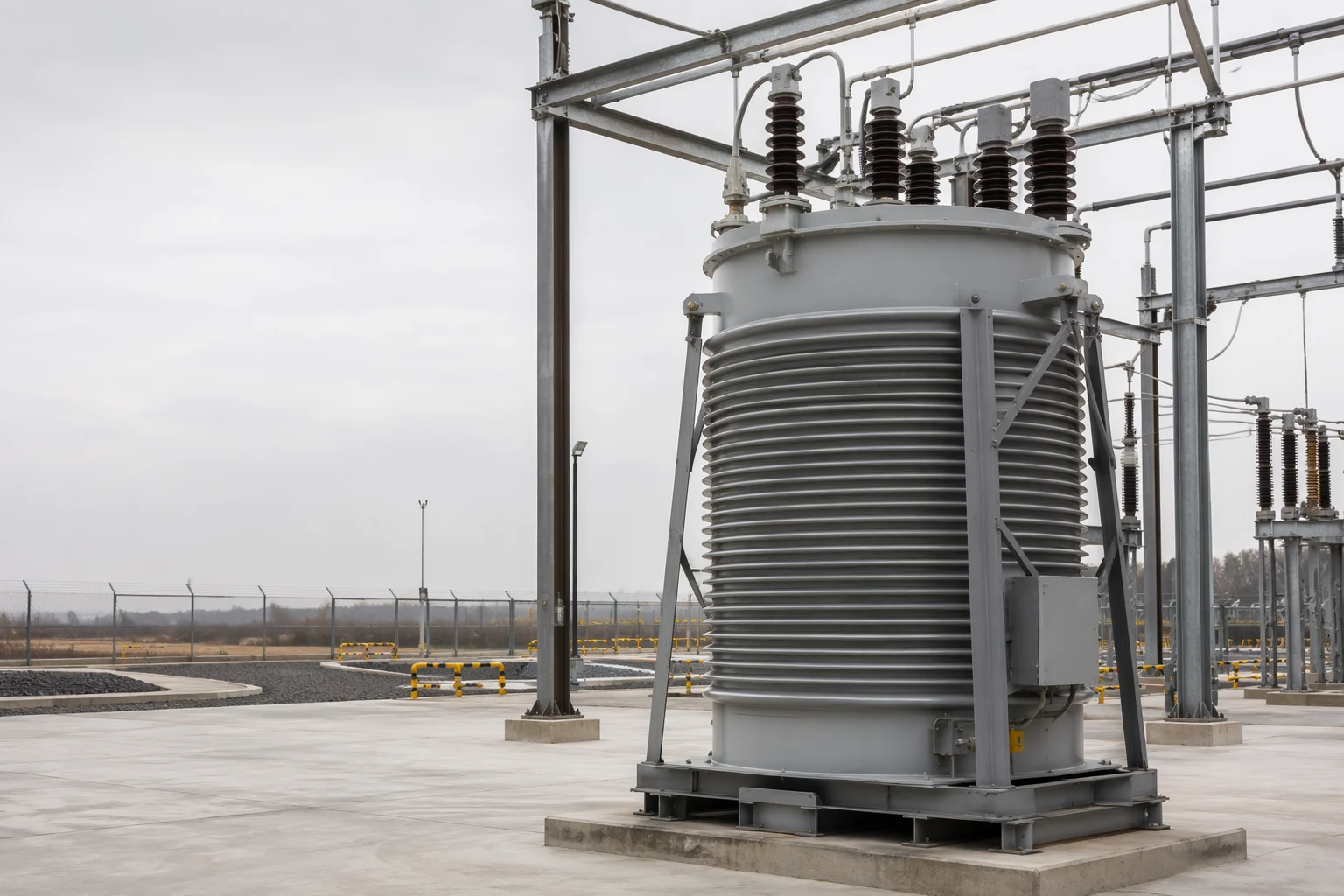
An arc suppression coil, also known as a Petersen coil or ground-fault neutralizer, is a tuned reactor connected between the neutral point of a power system and earth. Its purpose is to compensate for the capacitive earth-fault current produced by the network during a single-line-to-ground fault. By reducing the current that sustains the fault arc, the coil can improve transient fault performance and help maintain service continuity in appropriately designed medium-voltage distribution networks.
The device is becoming more important as distribution systems grow more complex. Renewable generation, underground cable, electric vehicles, battery storage, industrial electrification, and digital grid controls all change the electrical characteristics and operating states of networks. These changes can alter total capacitance, fault behavior, protection requirements, and the tuning point of the grounding system.
An arc suppression coil is not a universal replacement for protection, insulation coordination, or safe isolation. A properly engineered installation requires a coordinated study of network topology, earth-fault characteristics, residual current, overvoltage risk, protection scheme, operating procedures, and applicable national requirements.
What Is an Arc Suppression Coil?
An arc suppression coil is a high-inductance reactor used in a resonant-grounded or compensated-neutral system. It is normally connected from the system neutral to earth, either directly at the transformer neutral or through a grounding transformer when a suitable neutral point is not available.
- Arc suppression coil: emphasizes reducing current available to an earth arc.
- Petersen coil: the historical and widely used engineering name.
- Ground-fault neutralizer: describes the neutral-grounding function.
- Resonant grounding reactor: describes the electrical operating principle.
- Neutral grounding reactor: a broader term that can include other neutral-grounding arrangements.
The most typical application is a medium-voltage distribution network in which a temporary single-line-to-ground fault may occur on an overhead line, cable system, substation bus, or connected equipment. Suitability depends on the network fault philosophy and local utility practice; it should not be selected only because the equipment is commercially available.
How an Arc Suppression Coil Works
The capacitive current during an earth fault
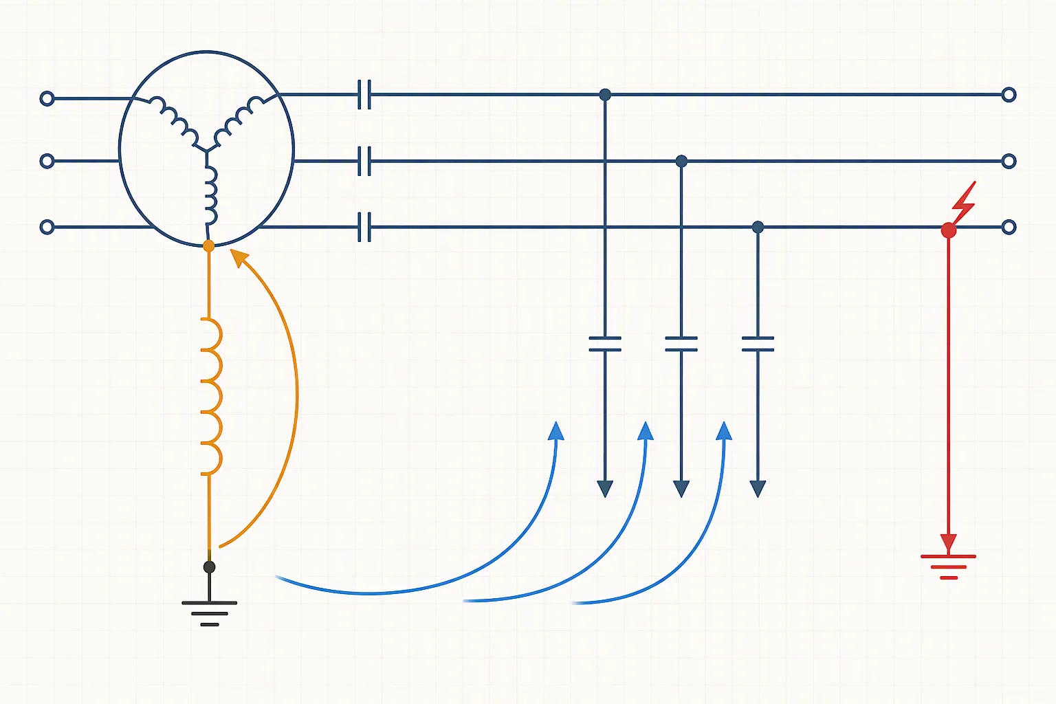
In a three-phase network, each phase has capacitance to earth through overhead lines, cables, transformers, surge arresters, connected equipment, and other elements. Under normal conditions, these capacitances produce a distributed capacitive current that is largely balanced.
When one phase is connected to earth, the voltage of the two healthy phases relative to earth increases. The resulting capacitive current flows through the healthy phases and returns through the fault path. This current can maintain an electrical arc at the fault point, especially when the fault is intermittent or occurs across air, vegetation, contaminated insulation, or a damaged line.
For a simplified engineering explanation:
IC ≈ 3ωCΣU0
Here, IC is network capacitive earth-fault current, ω is angular frequency, CΣ is equivalent phase-to-earth capacitance, and U0 is the corresponding zero-sequence or neutral-displacement voltage. The exact calculation depends on system model, grounding arrangement, line geometry, cable construction, transformer connections, and fault conditions.
Inductive compensation
The arc suppression coil creates an inductive current approximately opposite in phase to the network capacitive current:
IL ≈ U0/(ωL)
When inductive current is tuned close to capacitive current, residual current is reduced:
Ires ≈ IC − IL + Iloss
Iloss represents resistive, dielectric, harmonic, and other non-ideal components that are not canceled by an ideal reactor. The practical objective is to limit current and its rate of change sufficiently to reduce arc persistence while maintaining acceptable insulation and protection performance.
Why arc extinction is possible
A fault arc is influenced by more than current magnitude. Transient recovery voltage, voltage recovery rate, fault path, wind, contamination, moisture, and physical distance between conductors all affect whether the arc extinguishes or re-strikes.
Resonant grounding can improve the probability of arc extinction by reducing current through the fault and changing transient behavior. It does not eliminate the need to locate, isolate, and repair the faulty section. A low-current earth fault can remain hazardous and can develop into a more serious fault if not managed correctly.
Main Configurations
Fixed arc suppression coil
A fixed coil has a defined inductance selected for a particular network configuration. It is appropriate where the network is stable, total capacitive current is predictable, and switching arrangements do not significantly change the tuning requirement. Its limitation is detuning when feeders are connected or disconnected, overhead circuits are converted to cable, or distributed assets alter topology.
Tapped or adjustable coil
A tapped coil changes inductance through discrete tap positions. It offers a robust adjustment mechanism and easier integration with conventional substation control systems, with lower electronic complexity than fully power-electronic compensation. Design must account for tap-change interlocking, transient behavior, neutral displacement, mechanical endurance, and the possibility that no suitable tap exists for every operating state.
Continuously adjustable coil
A continuously adjustable coil uses a regulator or variable-inductance mechanism to track network capacitive current. Automatic regulation can use neutral voltage, zero-sequence quantities, or other indicators. The control system needs clear limits and fail-safe behavior because poor measurement quality, rapidly changing capacitance, harmonics, and switching transients can produce incorrect tuning decisions.
Coil with a grounding transformer
Where a substation lacks a suitable neutral point, a zig-zag grounding transformer or another appropriate transformer arrangement can create one. The transformer and reactor must be assessed as a combined system, including zero-sequence impedance, thermal duty, insulation level, neutral voltage, fault-current sharing, ferroresonance risk, and protection interactions.
Parallel damping or resistor arrangements
Some compensated-neutral systems include a damping resistor or auxiliary branch to improve fault detection, limit neutral displacement, damp oscillatory behavior, or support specific fault conditions. Adding resistance changes the fault-current waveform and protection problem and requires a complete grounding and protection study.
Engineering Design and Selection Considerations
1. Define network operating states
The first design question is the maximum and minimum network capacitance under every credible operating state, not simply system voltage. Consider bus-section and bus-coupler positions; feeders in service, out of service, or transferred; overhead and underground sections; cable construction, screen bonding and sheath arrangement; transformer winding connections and zero-sequence paths; distributed generation and storage; planned expansion; and emergency or maintenance configurations.
2. Estimate total capacitive earth-fault current
Calculate total capacitive current from a validated network model and check it against field measurements where possible. Procurement specifications should state nominal and highest voltage, frequency range, minimum and maximum capacitive current, fault duration, tuning range, permitted residual current, neutral displacement limits, harmonic and transient requirements, ambient temperature, altitude, enclosure, and cooling conditions.
3. Select the tuning philosophy
Utilities may use near-resonance operation, controlled under-compensation, controlled over-compensation, or a defined detuning margin. The selected philosophy must be coordinated with arc-extinction performance, fault detection sensitivity, neutral-point voltage, healthy-phase overvoltage, ferroresonance, switching behavior, and local utility rules. The tuning target should be documented as a system requirement.
4. Check overvoltage and insulation coordination
During a single-line-to-ground fault, the two healthy phases can experience increased voltage to earth. Check insulation systems, surge arresters, cable accessories, instrument transformers, switchgear, and connected equipment for temporary and transient overvoltages. IEC 61936-1:2021 addresses design and erection of electrical power installations above 1 kV AC, but it is not a product-specific arc suppression coil standard and does not replace local grid codes or project-specific insulation coordination.
5. Coordinate earth-fault protection
Resonant grounding reduces fault current, but smaller current can be more difficult to detect selectively. Protection may combine zero-sequence voltage supervision, residual-current measurement, transient analysis, harmonic or frequency-selective quantities, signal injection, directional earth-fault elements, feeder automation, communication-assisted logic, fault passage indicators, and distributed sensors. Test low-current, high-resistance, intermittent, and evolving faults.
6. Evaluate thermal and mechanical duty
Assess continuous current and losses, short-time current and duration, winding temperature rise, core flux and saturation, tap-changer duty and contact wear, switching transients, noise and vibration, enclosure ventilation and fire performance, environmental pollution, moisture, altitude and corrosion, and earthing of the tank, frame, cabinet, and auxiliary circuits. Traceable calculations, material certificates, routine tests, type-test evidence, and a clear factory acceptance procedure are more valuable than a catalogue rating alone.
Application Cases
Overhead medium-voltage feeder with transient faults
Lightning, vegetation, windborne debris, animals, and contaminated insulators can cause temporary or intermittent faults. Resonant grounding can reduce current available to an arc and may allow ride-through of some transient events, but operating philosophy must define tripping, fault location, and personnel protection. Engineering priority: arc-extinction performance with dependable fault indication and safe limits.
Urban network with mixed overhead line and cable
Cable sections usually contribute more phase-to-earth capacitance than comparable overhead sections, so current changes as feeders are added or transferred. An adjustable or automatically regulated coil can provide a wider range if measurement, control, and protection are engineered as one package. Engineering priority: a verified capacitance model, defined tuning range, and selective protection after compensation.
Industrial distribution with high continuity requirements
A process plant may limit interruptions caused by temporary earth faults, but must establish alarm, inspection, fault-location, and shutdown policies. Small fault current does not make a fault safe. Personnel access, touch voltage, equipment damage, and the possibility of a second earth fault remain under control. Engineering priority: continuity balanced against safety and time-to-repair.
Network with increasing distributed energy resources
Solar, wind, battery storage, and power-electronic interfaces change fault contribution, impedance, harmonics, and switching behavior. Include the coil in connection studies and grid-modernization projects, examining interactions with inverter controls, transformer grounding, relays, communications, and islanding or transfer schemes. Engineering priority: dynamic studies across normal and abnormal operating states.
Current Industry Trends
Grid modernization and adaptive grounding
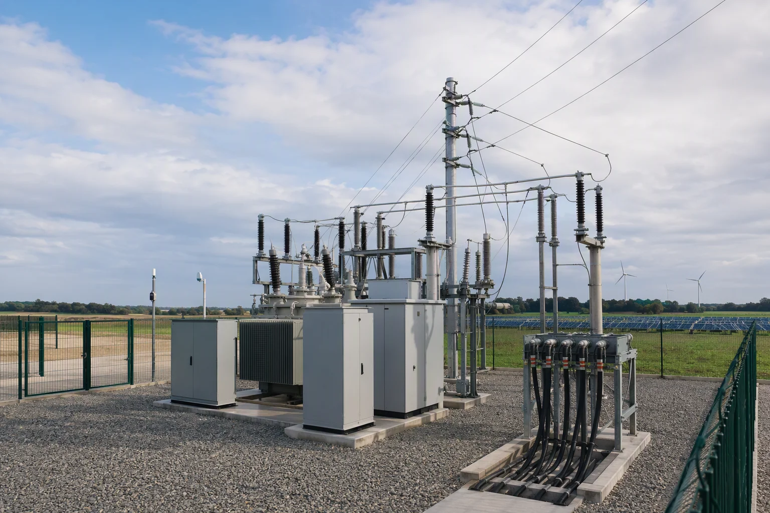
Grid modernization combines sensors, communications, automation, controls, analytics, storage, and other technologies to improve reliability and integrate new resources. Grounding equipment is increasingly part of a monitored substation and feeder-control system. Its value depends on reactor design, measurement quality, tuning logic, alarm management, and understanding network changes.
Automatic tuning and digital supervision
Research examines automatic tuning, signal processing, wavelet denoising, neutral-voltage measurement, and regulator behavior under changing capacitance. A modern specification may include online estimation of capacitive current, automatic or supervised tap selection, event recording and waveform capture, remote status and alarm communication, tuning-history records, cybersecurity controls, and simulation-based validation. Automation must remain bounded by voltage, current, tap-position, and protection interlocks.
Transient fault detection and fault-section location
Because compensation reduces steady-state fault current, fault location is difficult when protection relies only on magnitude. Current research focuses on transient signals, leakage-energy methods, harmonic quantities, signal injection, wide-area measurements, and data-driven fault-section identification. The trend is integration of coil, sensors, protection, automation, communication, and the engineering model into one fault-management architecture.
Lifecycle procurement and supply-chain discipline
Buyers should define requirements early, avoid ambiguous equivalent ratings, and evaluate long-term service capability as well as initial price. Compare guaranteed electrical performance and tuning range, standards and test evidence, reactor and grounding-transformer interfaces, spare parts and tap-changer support, firmware and cybersecurity documentation, factory and site acceptance tests, training, commissioning and troubleshooting support, and environmental end-of-life requirements.
Manufacturing and Quality-Control Perspective
Field performance depends on electrical design, magnetic materials, mechanical construction, insulation, cooling, and controls. Manufacturers should address core material and flux-density margin, winding geometry and insulation, mechanical forces, tap-selector or variable-inductance mechanisms, temperature-rise and loss measurements, partial-discharge and dielectric tests where applicable, terminal and bushing design, vibration and enclosure sealing, control-panel wiring and signal integrity, and calibration of voltage, current, and position sensors.
The key procurement question is whether the complete supplied system remains within its guaranteed performance envelope when the network is reconfigured, ambient conditions change, and controls operate under fault conditions.
Limitations and Safety Considerations
An arc suppression coil does not by itself guarantee that every arc will extinguish, that a faulted feeder can remain energized safely, that personnel can approach equipment, that earth potential rise is acceptable, that protection identifies every high-resistance fault, that healthy-phase overvoltage is harmless, or that tuning remains correct after expansion.
Projects should establish rules for alarms, inspection, fault location, isolation, temporary grounding, and return to service. Final designs must be reviewed by qualified power-system and protection engineers and aligned with utility rules, national regulations, occupational safety requirements, and equipment standards.
Practical Specification Checklist
- System data: voltage, frequency, neutral arrangement, short-circuit level, topology, overhead/cable lengths, and minimum/maximum capacitive current.
- Coil requirements: inductance or current range, fixed/tapped/continuous design, tuning philosophy, duty, insulation, losses, temperature rise, noise, enclosure, and environment.
- Control and protection: measurement accuracy, automatic tuning and manual override, tap indication and interlocking, alarms, fault recording, relay coordination, communications, remote access, and cybersecurity.
- Testing and documentation: design calculations, model assumptions, type and routine tests, FAT, site acceptance, commissioning, calibration, manuals, spares, service support, training, and emergency procedures.
Summary
An arc suppression coil is a resonant-grounding reactor that compensates the capacitive component of single-line-to-ground fault current. Its engineering value is reducing current available to sustain an arc, which can improve transient fault performance in suitable medium-voltage systems.
The design challenge is system-level: calculate capacitance across operating states, select tuning philosophy, verify overvoltage and insulation coordination, coordinate low-current protection, and define safe procedures. Procurement should specify the complete reactor, grounding transformer, control, monitoring, protection, testing, and service package. As grids become more renewable-rich, cable-intensive, automated, and variable, the trend is from a passive manually adjusted reactor toward a monitored adaptive fault-management system. Digital tuning and transient detection improve performance but do not remove the need for conservative engineering and qualified operational control.
Reference Directions
- International Energy Agency: Building the Future Transmission Grid and Electricity Grids and Secure Energy Transitions.
- U.S. Department of Energy: Grid Modernization and the Smart Grid.
- IEC 61936-1:2021: high-voltage installation design and erection.
- Public research examples: flexible neutral-point potential regulation, fault-section location in arc-suppression-coil networks, and recent studies in Energies on arc extinction and high-impedance grounding-fault protection.