
Introduction
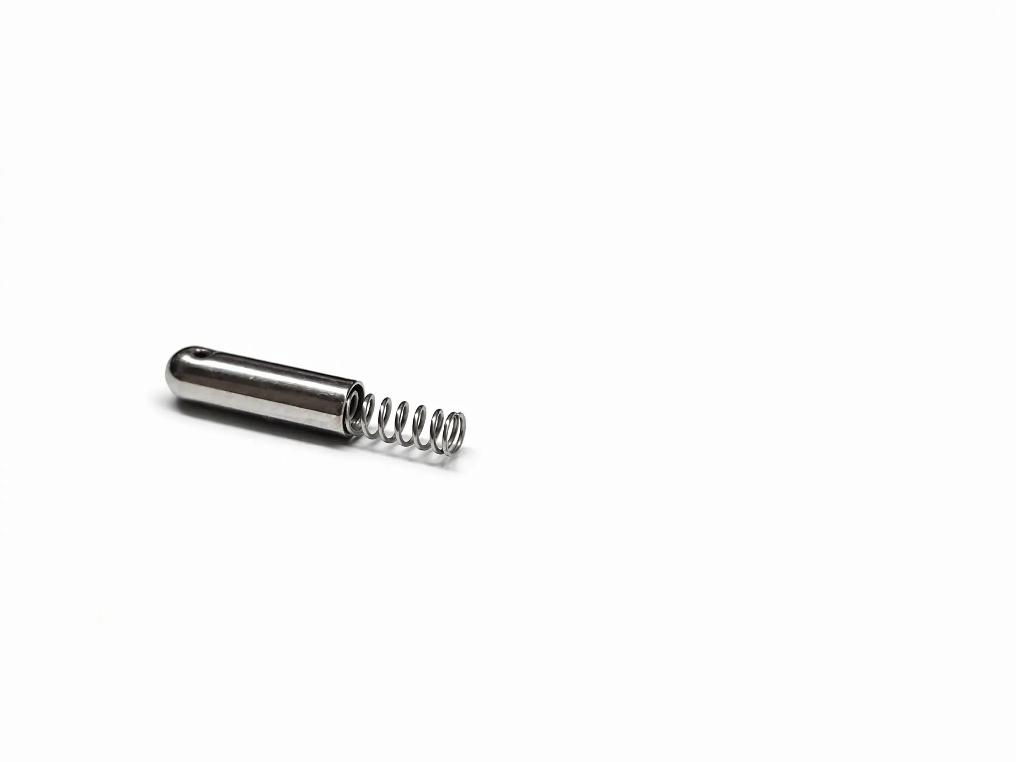
An archery bow spring pin is a small two-part assembly: a turned metal pin body with a spring loaded behind it, used to provide locating, detenting, or quick-release locking action inside bow accessories. In practice, the body is a short stainless steel cylinder about 3 to 12 mm long with a bored tail, a cross hole or shoulder at the head, and a compression spring seated in the bore.
The part looks simple. However, it is not. Above all, its function depends on the interaction of four things that are easy to specify badly: pin-to-bore clearance, spring rate, spring preload, and surface finish. For instance, a pin that is 0.02 mm oversize will bind in a painted sight housing. A spring that is 20 percent too stiff makes a detent feel like a jam. A passivation step that is skipped will show rust on a customer’s bow after two rainy hunts, and the complaint will not be about chemistry – it will be about your brand.
This guide covers the anatomy of the part, the materials and finishes used in bow and crossbow accessories, the design parameters that should appear on a drawing, the failure modes seen in the field, the manufacturing route, and the specification checklist to send with an RFQ.
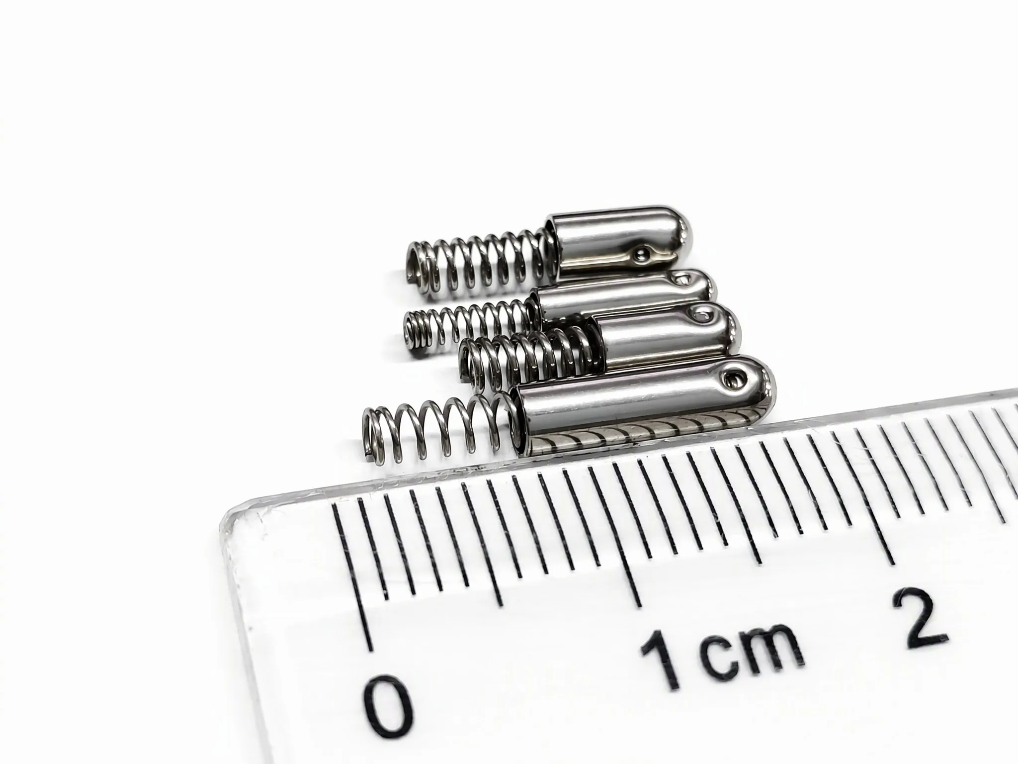
What Is an Archery Bow Spring Pin?
In archery hardware, this component is usually a spring-loaded pin, sometimes called a spring plunger pin, detent pin, or spring-loaded detent. Its job is one or more of the following:
- Locating: hold a sight housing, arrow rest launcher, or quiver bracket in a repeatable position.
- Detenting: give a click or index feel at defined adjustment increments (elevation, windage, or pin-selector positions).
- Quick release: allow a tool-free attachment such as a detachable quiver or stabilizer mount to be locked and removed.
- Preloading: take up clearance so a joint does not rattle under bow vibration.
- Spring return: push a lever, latch, or launcher back to its rest position.
In addition, the pin body usually carries a cross hole or a groove so it can be retained by a split pin, a shoulder screw, or a roll pin, while the spring provides the axial bias. In other words, this is what distinguishes the part from a plain dowel: the spring stores the energy, the pin transmits the motion, and the housing controls the direction.
Naming problem: “spring pin” is not the same part
Because the component has no single accepted name, search demand splits across several names, and buyers often use them interchangeably. Nonetheless, they are not interchangeable in engineering terms, and mixing them up in an RFQ is a common cause of wrong samples.
| Term | What it actually is | Typical standard or form |
|---|---|---|
| Spring pin (coiled) | Hollow cylindrical pin made from coiled strip, pressed into a hole and held by radial interference | ISO 8750 type |
| Spring pin (slotted) | Hollow slit pin, also known as a roll pin or split spring dowel | ISO 8748 / DIN 1481 family |
| Spring loaded pin | Solid or bored pin with a separate compression spring behind it; the part in this article | Custom drawing |
| Detent pin / plunger | Pin with a rounded or chamfered nose that indexes into a groove or notch | Custom, often with ball |
| Ball plunger | Threaded body containing a spring and a ball | Off-the-shelf hardware |
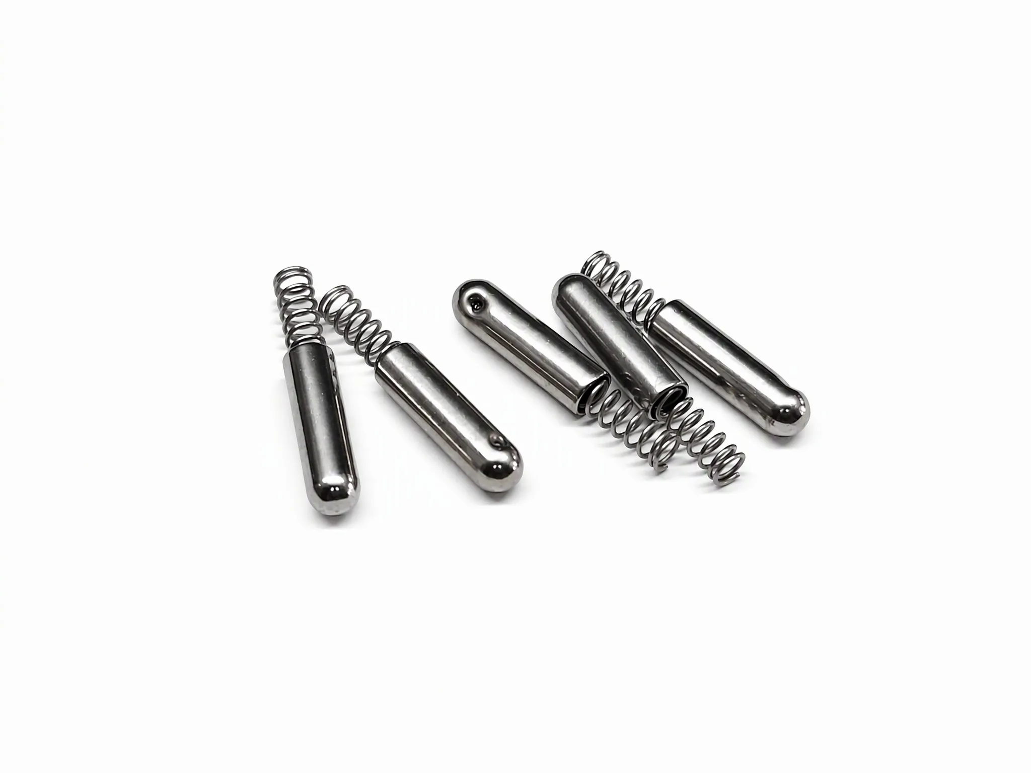
For SEO and catalogue purposes, the phrase “archery bow spring pin” is acceptable as long as the drawing supplied to the supplier shows the actual geometry. On a drawing, describe the part by function – for example “spring-loaded locating pin, 4 mm diameter body, 6 N preload” – rather than by a trade name that also describes a hollow dowel.
Anatomy of the Assembly
1. The pin body
The body is normally machined from bar stock on a Swiss-type lathe, which allows the small diameters, tight concentricity, and fine surface finish this part requires. Features that appear on a typical drawing:
- Outside diameter, often 2 mm to 8 mm, with an h9 or f7 tolerance band depending on whether the pin slides or is fixed.
- A bored tail to receive the spring, with a bore depth that controls installed length and spring preload.
- A head form: domed, flat with chamfer, shouldered, or with a cross hole for a retaining pin.
- A nose form: chamfered for lead-in, radiused for detent travel, or flat for load-bearing.
- A groove, flat, or anti-rotation feature when the pin must not rotate in its housing.
Notably, concentricity of bore to outside diameter, and squareness of the shoulder, matter more than most drawings admit. If the bore is off-axis, the spring pushes at an angle, the pin cocks in the bore, and friction rises on one side. As a result, inconsistent actuation force appears from unit to unit – the classic “some are smooth, some are sticky” complaint.
2. The cross hole
The hole near the head is usually a retention feature: a split pin, a safety wire, a shoulder screw, or a cross pin passes through it and limits travel. When the pin is captive in a housing, the hole also prevents the assembly from being pulled out during accessory removal.
For this reason, hole position tolerance, burr control, and breakout condition all matter here. For example, a burr left inside a 1 mm hole will rub the mating pin and create false drag; a hole drilled after passivation exposes fresh, unpassivated material inside the bore.
3. The compression spring
The spring is a small helical compression spring, commonly 0.2 mm to 0.6 mm wire diameter, with 4 to 10 active coils. In this class of part it does three jobs: generate the preload, define the feel of the detent, and absorb tolerance stack so the assembly does not rattle.
Key spring parameters on the drawing:
- Wire diameter and material grade.
- Outside or inside diameter with a clearance fit to the bore.
- Free length and installed length.
- Solid height, which must be shorter than the minimum working length or the spring will be overstressed before full travel.
- Spring rate in N/mm, or a load at two defined lengths.
- Ends: closed and ground, closed not ground, or open. For short springs in a small bore, closed-not-ground ends are common because grinding a 0.2 mm wire spring to square is expensive and rarely justified.
- Direction of wind, when the assembly has a thread or a handed mechanism.
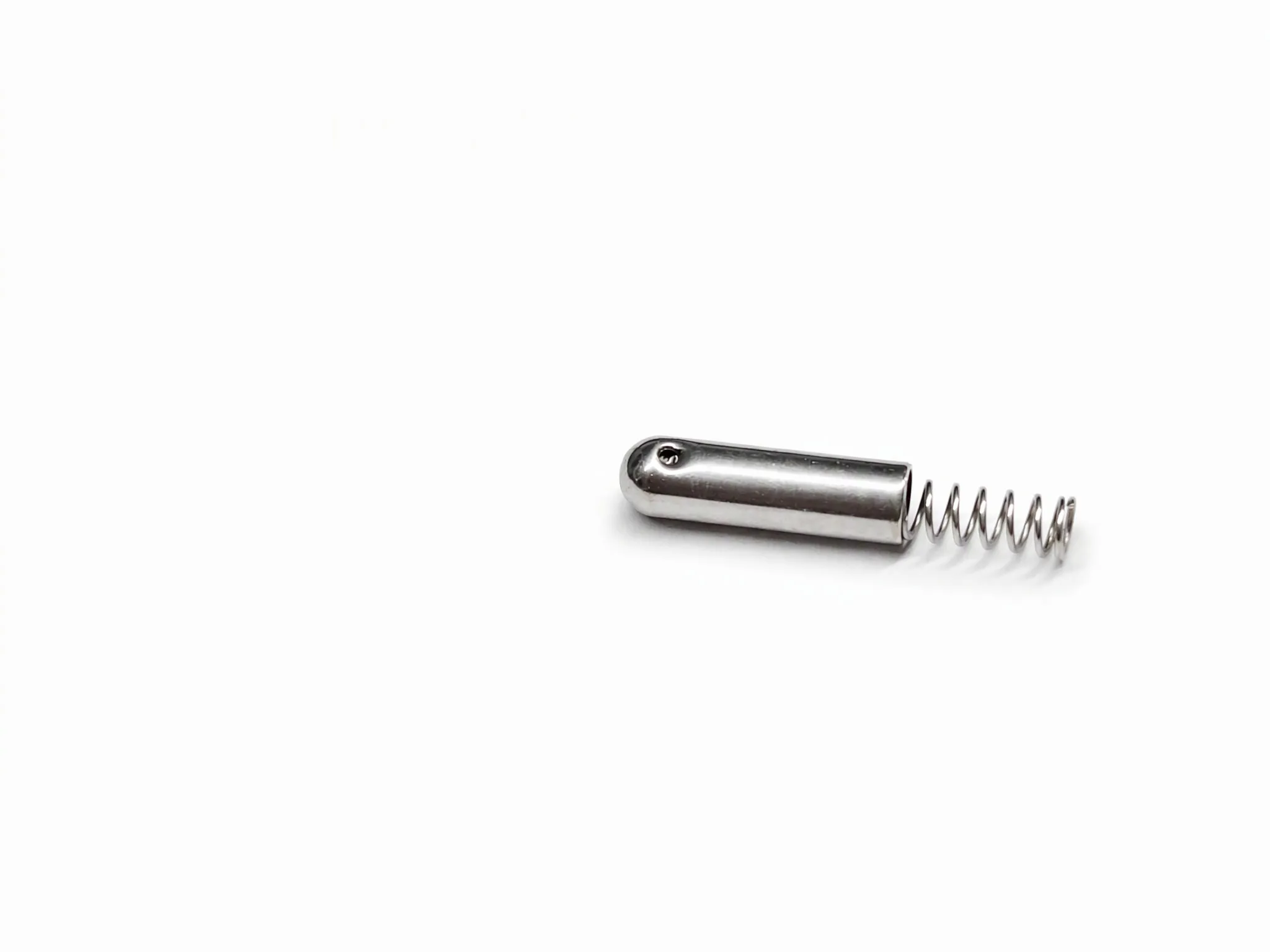
4. The joint between body and spring
The spring can be retained in the body in several ways, and the choice drives cost, serviceability, and failure risk:
| Retention method | How it works | Advantage | Risk |
|---|---|---|---|
| Loose / captive in housing | Spring sits in the bore, retained only when the pin is installed | Lowest cost, easy assembly | Spring can be lost during field service; assembly error is possible |
| Press fit / interference | Spring end is pressed into a slightly undersized bore | No extra process, self-retaining | Bore tolerance must be tight; wire coating can be scraped |
| Staked or swaged | Bore edge is deformed over the spring’s end coil | Mechanical lock, no adhesive | Deformation can jam the first coil; hard to inspect |
| Threaded | Spring end formed into a thread or attached to a threaded stud | Serviceable | Added cost, torque control needed |
| Adhesive | Retained with a structural or thread-locking adhesive | Cheap, damps vibration | Temperature limit, cure control, cleanliness sensitivity |
| Laser weld / braze | Spring leg welded to the body | Strongest, good for high shock | Heat affects spring temper unless local and controlled |
In practice, most archery accessories leave the spring free in the bore or lightly staked. By contrast, welding is used when the part sees repeated shock, such as a string stop or a launcher return.
What the Pin Actually Does: Load Path and Feel
Preload defines the detent feel
In effect, a detent pin has to do two contradictory things: hold position against vibration, and release smoothly when the user adjusts it. Consequently, both are governed by the preload and rate of the spring, not by the pin diameter.
As a practical starting point for hand-operated bow accessories, actuation forces in the range of roughly 5 N to 15 N are typical for a thumb or finger operated adjustment, while a positive lock that must not release under bow shock may be specified higher. These are design starting points, not universal values: the correct number depends on the lever the user has, whether gloves are worn, and whether the detent must survive a fall.
The vibration environment is the real test
A compound bow releases a large amount of energy in milliseconds. As a result, everything bolted to the riser sees high-frequency vibration and repeated shock. A pin that tests perfectly on a bench can still develop three field problems:
- Creep and relaxation: the pin slowly backs out of its detent because preload is marginal and vibration walks it out.
- Fretting: small relative motion between pin and housing wears through passivation and starts corrosion at the contact line.
- Spring set: the spring takes a permanent set after thousands of cycles, so the actuation force drops and the part feels loose.
Therefore, good design addresses all three – higher preload margin, harder or coated contact surfaces, and springs specified below about 40 to 45 percent of tensile strength at the working length so that relaxation stays predictable.
Guide, locate, lock
Functionally, distinguish three jobs before choosing tolerances:
- Guide: the pin slides in a bore. Clearance must be large enough to avoid binding after coating or thermal change, small enough to avoid visible play. A clearance of a few hundredths of a millimetre is normal at 4 mm diameter; the acceptable value follows from the play the user can feel.
- Locate: the pin establishes a repeatable position. Concentricity and bore-to-outer-diameter tolerance dominate; the sliding fit matters less than the datum.
- Lock: the pin carries load. Then the shear area, the hardness of the mating notch, and the nose radius determine life, and the spring only has to hold engagement.
Material Selection
Body material
| Material | Typical use | Notes |
|---|---|---|
| 303 stainless | General purpose, high-volume turning | Free-machining; lower corrosion resistance than 304; residual sulfur can stain in humid storage |
| 304 / 304L stainless | Standard bow accessory pins | Good general corrosion resistance, good formability, widely available |
| 316 / 316L stainless | Bowfishing, saltwater, coastal hunting | Molybdenum addition improves chloride resistance; slightly gummier to machine |
| 17-4 PH stainless | Load-bearing pins, high strength | H900 condition gives high strength; must be passivated after machining |
| Brass (C36000) | Decorative or low-load pins, plated | Easy to machine and plate; not for high-load or wear-critical use |
| Aluminium 6061-T6 | Weight-critical non-load parts | Anodize required; poor wear resistance at sliding contact |
| Titanium Grade 5 | Premium weight saving | Expensive, galling-prone, needs coating or dry-film lubricant at sliding surfaces |
Selection logic therefore runs in this order: corrosion environment first, load second, weight third, cost last. For example, a bowfishing pin in 303 will rust, whereas a target-archery pin in Grade 5 titanium is an unnecessary cost that also brings galling risk.
Spring wire
- Music wire (ASTM A228 type): highest tensile for its diameter and cheapest, but not corrosion resistant. Only suitable if the spring is protected or the environment is dry and controlled.
- 302 stainless (ASTM A313 302): the default for bow hardware. Good fatigue behavior, adequate corrosion resistance, widely available in small diameters.
- 316 stainless: better chloride resistance for coastal and bowfishing use, with somewhat lower tensile strength and fatigue performance than 302 at the same diameter.
- Elgiloy / cobalt-nickel alloys: used where space is extremely tight and the spring must survive high stress cycles; cost is significantly higher.
- Phosphor bronze: non-magnetic and good in some marine conditions, but lower strength; occasionally used where magnetic interference matters.
If a pin is used near a magnetic sight or a magnetic nock system, note that 300-series stainless is generally non-magnetic in the annealed condition but can become slightly magnetic after cold working. Test rather than assume.
Finish and friction
Archery parts live in rain, mud, sweat, camo dip, and salt. Finishes that appear on this component:
- Passivation (ASTM A967 / ASTM A380 practice): removes free iron and supports the natural chromium oxide layer. It is not a coating and does not hide scratches; it is the minimum requirement for stainless parts.
- Electropolishing: improves surface finish and corrosion resistance, removes micro-burrs inside the bore, and reduces friction. Useful on pins that must slide smoothly.
- Black oxide: cosmetic and mildly lubricious, with limited corrosion protection unless oiled.
- PTFE or dry-film lubricant: lowers sliding friction and reduces galling on stainless-to-stainless contact. Good for titanium and for tight-clearance pins.
- DLC or hard coatings: for high-cycle wear surfaces; rarely cost-justified on a small detent pin.
- Anodizing (aluminium only): adds a hard, dimensionally stable layer but changes the bore size; specify bore after anodizing.
In practice, thickness control is the chronic issue with plated parts: if the bore is plated, the spring fit changes; if only the outside is plated, the plating edge becomes a corrosion site. As a result, specify which surfaces are functional and which are cosmetic.
Design Parameters That Belong on the Drawing
A spring pin drawing that shows only a diameter and a length cannot be quoted or inspected reliably. The following parameters carry the function, and each should have a nominal value, a tolerance, and a verification method.
Geometry and tolerance
| Parameter | Typical value or band | Why it matters |
|---|---|---|
| Body outside diameter | 2 to 8 mm, h9 or f7 | Controls fit: sliding versus fixed |
| Bore diameter | 0.1 to 0.3 mm larger than spring OD | Loose spring = rattle, tight spring = binding |
| Bore depth | Sized so installed length equals working length | Directly sets preload |
| Cross hole diameter and position | As required, position within about plus or minus 0.05 mm | Retention and travel limit |
| Head shoulder squareness | 0.02 mm or better | Seats flat, avoids cocking |
| Overall length | As required, +/-0.05 mm typical | Assembly stack-up |
| Edge break | 0.05 to 0.15 mm chamfer, burr-free | Prevents seal and coating damage, removes scratch risk |
| Surface finish | Ra 0.4 to 0.8 micrometre on sliding surfaces | Lowers friction, improves corrosion resistance |
General tolerances on a drawing are frequently misused: a note such as “general tolerance ISO 2768-m” is fine for non-functional features, but pin diameter, bore, and hole position must be toleranced individually because they are functional.
Spring specification
State the spring in mechanical terms rather than by drawing shape only:
- Rate k (N/mm) or a two-point load requirement, for example 8 N at 5.0 mm and 14 N at 3.5 mm.
- Free length and solid height, with solid height at least 15 to 20 percent below the minimum working length to leave reserve travel.
- Preload at installed length, which is what the user feels as the initial detent.
- Maximum stress at solid height, kept below roughly 40 to 45 percent of the wire’s tensile strength for a long-life spring, and below about 55 percent for limited-cycle applications. Pushing a small spring near its solid height is the single most common cause of short life in this class of part.
- Set removal (presetting): a manufacturing step in which the spring is compressed to solid once or twice so that the first-cycle loss of length happens in the factory, not in the customer’s bow.
Actuation force window
Buyers often specify “smooth action” as a requirement. However, that is not inspectable. Replace it with:
- Breakaway force to release the detent (N).
- Running force during adjustment (N).
- Return force at rest (N).
- Allowed variation across a production lot, for example plus or minus 15 percent.
- Test method: compression at a defined speed between flat platens, force measured with a load cell, sampled from each lot.
Cycle life
For a sight or rest adjustment pin, life is often specified in adjustments. For a launcher return or latch, life is specified in shots. Therefore, a sensible validation plan tests at least 10,000 cycles for adjustment detents and 20,000 to 50,000 cycles for a shot-actuated spring, with force measured before and after. The pass criterion should include a maximum allowed force loss, for example 20 percent, not just “no breakage.”
Corrosion requirement
Neutral salt spray testing to ISO 9227 (NSS) is the usual reference. What matters, however, is that the requirement is written for the actual material and finish, and that acceptance criteria are specified: no red rust on functional surfaces after a defined number of hours, and no change in actuation force after the test. A number quoted without a finish specification is meaningless, because passivated 304 and 303 behave differently, and any plated part behaves differently again.
Temperature and contamination
Meanwhile, a bow left in a vehicle can exceed 60 C; a winter hunt can be well below freezing. Specify the operating range, for example -20 C to +60 C, and confirm the spring material and any adhesive or lubricant remain valid across it. Lubricant choice matters too: a grease that thickens at low temperature will double the actuation force at -10 C.
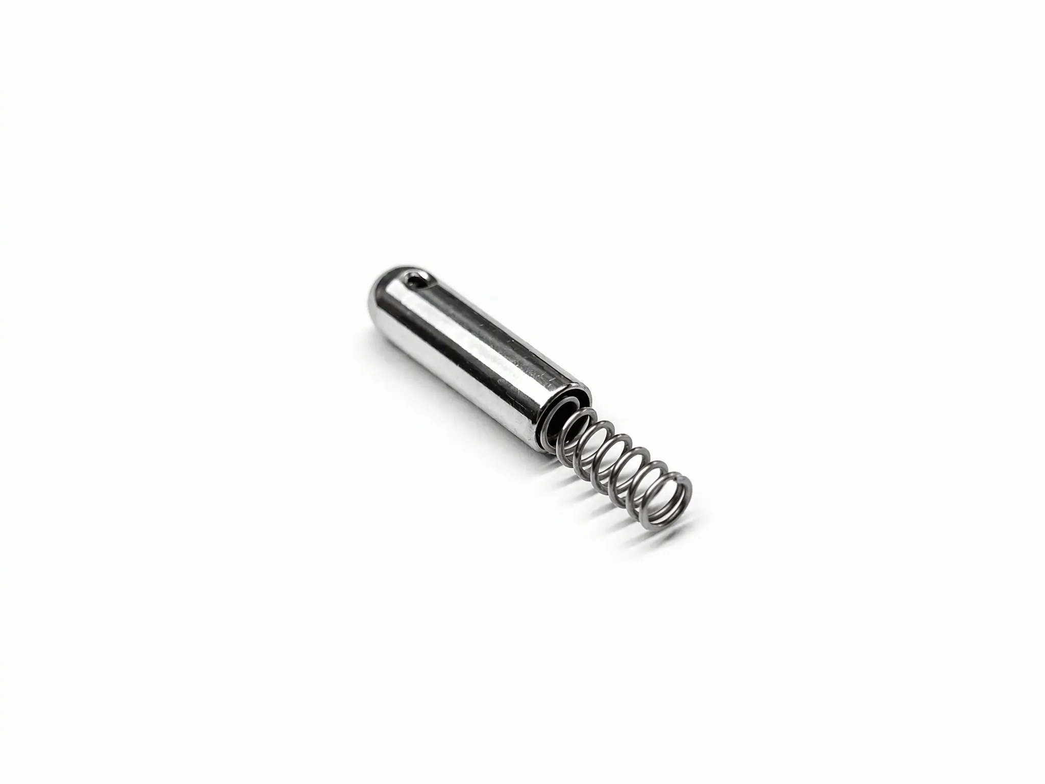
Common Failure Modes and Their Causes
1. Spring fatigue or permanent set
Symptom: the pin no longer holds its position, or the click feel becomes weak within a season.
Cause: the spring is stressed too high at working or solid height, the wire diameter is at the low end of tolerance, or the spring was never preset. Small springs with few coils are especially sensitive because the end coils contribute little deflection but consume length.
Fix: specify stress at solid height, require presetting, and control wire diameter with a two-sided tolerance rather than a nominal.
2. Corrosion at the contact line
Symptom: brown staining or pitting, usually first at the bore edge, the cross hole, or where the spring touches the body.
Cause: missing passivation, embedded iron from a carbon steel brush or a shared tumbling line, residual machining coolant in a blind bore, or galvanic couple with an aluminium housing in wet conditions.
Fix: control the process chain, not just the material certificate – dedicated stainless tooling, clean deburr media, and a documented passivation step after all machining including hole drilling.
3. Binding or inconsistent actuation
Symptom: some units are smooth, others stick; force varies from lot to lot.
Cause: bore-to-outside-diameter eccentricity, a burr in the cross hole, plating build-up in the bore, spring OD at the high end plus bore at the low end, or a bent spring caused by installation.
Fix: specify concentricity, deburr before passivation, inspect the first article on a profile projector or vision system, and set a clearance window rather than nominal dimensions for bore and spring OD.
4. Spring loss in the field
Symptom: customer receives a pin with no spring, or the spring falls out during accessory removal.
Cause: the spring was only retained by the mating part and the design allows the pin to be removed during normal use.
Fix: stake, press, or adhesive-retain the spring, or design the housing so the pin cannot be withdrawn past the spring seating depth.
5. Wear and notch formation on the nose
Symptom: the detent becomes mushy, or the pin will not index cleanly into its notch.
Cause: nose geometry too sharp, mating notch too soft, or contamination acting as an abrasive. For this reason, a radius on the nose spreads contact stress, whereas a sharp edge concentrates it and hammers a groove into a soft aluminium housing.
Fix: radius the nose, harden or anodize the mating part, and add a wiper or seal where mud ingress is possible.
6. Galvanic and thread-locker problems
In addition, an aluminium housing plus a stainless pin in a wet environment is a classic galvanic pair; the aluminium becomes the anode and the bore grows. Similarly, thread-locking adhesive used to retain a spring can also wick into the sliding clearance and lock the pin. In both cases these are design and assembly-process issues, not supplier defects, but they end up as warranty claims if they are not addressed on the drawing and in the work instruction.
Manufacturing Route
Step 1: Bar stock and turning
Swiss-type CNC turning is the standard route for this geometry. Specifically, bar diameter is chosen close to the finished outside diameter to minimize material removal and keep grain flow along the part. Typical sequence: face, turn OD, drill and bore the tail, drill the cross hole (often on a second operation or a sub-spindle), part off, chamfer both ends.
For high volumes, cold heading followed by secondary machining can reduce cost, but the tight bore concentricity usually favors turning unless the design allows a through hole.
Step 2: Deburring and cleaning
Still, cross holes in small stainless pins are the main burr source. Electrochemical deburring, abrasive flow, or controlled tumbling are used depending on hole size and burr specification. For this reason, blind bores must be cleaned of chips and coolant before assembly; a chip trapped under the spring will change preload and can jam the pin.
Step 3: Spring coiling and stress relief
Springs are coiled on CNC spring formers, then stress-relieved at a temperature appropriate to the wire grade. Accordingly, stainless springs are stress-relieved at a lower temperature than music wire and must not be heated into the sensitization range for the grade. Presetting to solid height follows, then a load test at the working length.
Step 4: Surface finishing
Passivation is performed after all machining, including the cross hole, and after any tumbling. Electropolishing, if specified, removes 2 to 5 micrometres of material and must be accounted for in the pre-finish dimensions, particularly in the bore.
Step 5: Assembly and retention
Manual or semi-automatic assembly with a force or depth check. In addition, the assembly station should verify that the spring is present, seated to the correct depth, and not bent. This is where most field failures are actually created, and where a simple poka-yoke – a depth sensor or a vision check for spring presence – pays for itself.
Step 6: Inspection
A practical inspection plan for this part:
| Check | Method | Frequency |
|---|---|---|
| Outside diameter, bore, length | Micrometer, pin gauge, optical comparator | First article plus sampling |
| Cross hole position | Vision system or CMM | First article plus sampling |
| Burr and edge break | Visual, 10x to 20x magnification | Each lot |
| Spring installed length and preload | Load cell at defined length | Sampling per lot |
| Actuation force in housing | Functional gauge simulating the customer housing | Each lot, ideally 100 percent on critical programs |
| Corrosion | ISO 9227 NSS on coupons or finished parts | Per finish qualification and periodic audit |
| Cleanliness | Visual and wipe test for chips and residue | Each lot |
| Material and finish certification | Mill cert plus process cert | Each lot |
| RoHS / REACH compliance | Declarations and, where required, test reports | Annual or per change |
That said, the functional gauge is worth emphasizing. Measuring a spring on a load cell tells you the spring is right; measuring the assembled force in a housing that replicates the customer’s bore, surface finish, and lubrication tells you the product works. The two are not the same test.
How to Specify the Part in an RFQ
Therefore, a complete RFQ for an archery bow spring pin contains eight items. Because of this, suppliers who receive all eight quote accurately; suppliers who receive three quote a guess.
- Drawing in PDF plus a STEP file, with functional dimensions toleranced and datums defined.
- Material and finish for body and spring separately, with the applicable standard and any restriction such as “no sulfurized free-machining grades.”
- Spring requirement as rate or two-point loads, installed length, solid height, and maximum stress at solid.
- Functional requirement: actuation force window, travel, and the housing bore and material it will run in.
- Life and environment: cycle count, temperature range, corrosion test and acceptance criteria, cleaning or lubricant exposure.
- Quality documents: first article report, material certificates, process certificates for passivation and any plating, and compliance declarations.
- Packaging and traceability: lot marking, bag quantity, and whether parts must be supplied assembled and function-tested.
- Volume and cadence: annual quantity, release size, and whether the design is likely to be revised.
Moreover, two procurement realities are worth planning for. First, tooling and setup dominate the price of a small turned part; a 20 percent diameter change usually costs less than adding a second operation or a new cross-hole fixture. Second, the cost of a wrong sample is almost never the sample price – it is the two weeks of engineering time, the customer’s delayed launch, and the risk that the brand ships with a pin that sticks.
Cost drivers, in order of impact
- Number of operations (cross hole on a second machine is expensive).
- Material grade (316 and 17-4 PH carry both material and machining cost).
- Tolerance class, especially concentricity and bore-to-OD.
- Surface finish (electropolishing, DLC).
- Spring complexity (fine wire, tight rate window, presetting, load testing each piece).
- Inspection and documentation level.
Application Scenarios: Where the Archery Bow Spring Pin Is Used
In fact, the same nominal part – a pin, a spring, a bore – is specified very differently depending on where it sits on the bow. What follows are the scenarios that generate most custom inquiries, with the design priority that actually decides whether the part succeeds in each one.
Scenario 1: Bow sight elevation and windage detents
Indeed, this is the highest-volume application and the one with the most demanding feel requirement. A target or 3D sight adjusts in small, repeatable increments; the detent pin indexes into a slot or a row of notches on the elevation bar or the windage block, and the archer moves two or three clicks between distances.
What the pin must deliver:
- Repeatable position. The archer returns to the same mark every end. A pin with excess clearance lets the housing settle in slightly different positions, and the group opens at 50 m without any obvious cause.
- Audible and tactile confirmation. A click the archer can hear and feel through a tab is worth more than a smooth action, because it removes doubt during a timed end.
- Force that does not change with temperature. A sight left in a hot car and then shot in cold morning air must index the same way.
- No walking. Vibration must not move the detent out of its notch between shots.
The design priority here is spring rate consistency and nose geometry, not load capacity. A 0.3 mm wire spring with five active coils and a tightly controlled installed length will outperform a heavier spring with a loose rate window, because the felt click depends on the rate, not on the wire size.
Scenario 2: Quick-detach sight bracket lock pin
By contrast, hunting sights are commonly removed to fit a hard case or to switch between a pin sight and a scope. A spring loaded pin locks the dovetail or the bracket to the riser and is pulled back with a thumb to release.
This scenario is therefore about retention under shock plus zero-loss repeatability. Two failures end up in warranty claims:
- The pin releases under bow vibration or when the bow is laid down, and the sight falls off in the field.
- The pin releases correctly, but the bracket reseats in a slightly different position, so the archer’s 30 m pin is now hitting 10 cm left.
The first is solved with preload margin and a deeper engagement; the second is solved by making the pin a locating feature with a hard, repeatable seat rather than a friction clamp. If the bracket uses the pin only as a latch and relies on a screw for position, the drawing must say so, because the two designs need different tolerances.
Scenario 3: Arrow rest launcher and drop-away actuation
On a drop-away rest, by contrast, the launcher is held up by a spring or a magnet and released by a cord attached to the buss cable. Spring loaded pins appear as the activation plunger, the thumb-cord latch pin, and the travel stop.
Requirements differ from a sight detent in one important way: the pin moves on every shot. In other words, a 200-shot practice week becomes 10,000 cycles in a season, and the spring is cycling far faster than on an adjustment detent.
- Specify cycle life in shots, not in adjustments.
- Keep stress at working length well below the fatigue limit, because coil fatigue, not corrosion, is the dominant failure mode.
- Control the launcher return force, since too strong a return spring can bounce the launcher and produce fletching contact.
- Expect contamination: dust, bowstring wax, and fletching adhesive all migrate into the bore. A slightly larger clearance with a PTFE-coated pin often outlasts a tight, unlubricated fit.
Scenario 4: Quiver quick-detach mount
Meanwhile, a bow quiver is removed and refitted several times in a hunt, often with cold hands and gloves. The spring loaded pin locks the quiver bracket to the riser mount, and the archer pulls it to detach.
The design priority is therefore one-hand operation with gloves and a positive lock that cannot be bumped open. Practical implications:
- Actuation force high enough to resist accidental release, but shaped for a gloved thumb – a knurled or shouldered head matters more than 2 N of force either way.
- Engagement depth sufficient that a partial pull does not release the quiver.
- A captive design or a staked spring, because a quiver pin is the part most likely to be disassembled by the customer and the spring is the part most likely to be lost.
- Corrosion resistance for the whole assembly, including the spring, since the quiver sits on the outside of the bow in rain and snow.
Scenario 5: Limb pocket and takedown alignment
On takedown, ILF, and some bolt-down interfaces, locating pins establish the limb position, while a separate bolt provides the clamping force. The spring loaded version allows the limb to be seated or released without tools.
Here the pin is a locating datum, so the requirement shifts from feel to geometry: pin diameter, hole position, and perpendicularity to the pocket face control arrow flight and tiller. For example, a pin that is 0.05 mm off in position moves the limb pocket, and the bow tunes differently left to right.
This is also the application where the pin carries the highest risk if it is undersized. A locating pin that is loose in its hole will allow the limb to shift under load, and the resulting inconsistency is usually blamed on the archer’s form before the hardware is suspected.
Scenario 6: String stop and damper rods
A string stop uses a rubber bumper on a rod, and some designs use a spring loaded element to soak up the remaining high-frequency vibration after the string contacts the bumper. The pin functions as a plunger with a spring behind it.
This is a shock application rather than a feel application. Consequently, the spring sees short, high-amplitude loads thousands of times, and the failure signature is a spring that sacks out and a rod that starts to rattle. Specify the spring for fatigue at the working length, keep solid height well clear of the travel, and prefer 302 stainless wire with a preset. A staked or welded retention is often justified here, because a loose spring in a vibrating rod is a noise complaint waiting to happen.
Scenario 7: Stabilizer and accessory quick-disconnect
In addition, front and side stabilizers, and the accessory brackets that carry them, frequently use a spring loaded pin as the quick-disconnect latch. Because the user mounts and removes the stabilizer between sessions, the same balance point must return afterward.
The requirement is positional repeatability plus load capacity, because the stabilizer hangs on the joint as a cantilever. The pin is not the only load path – a taper or a shoulder should carry the bending moment – but if the pin is drawn as the locating feature, its diameter and the hardness of the mating bore determine whether the joint develops play after a season.
Scenario 8: Bowfishing reel mounts and safety pins
Overall, bowfishing is the harshest environment in archery: saltwater, mud, weed, and repeated immersion. A spring loaded pin here holds the reel bracket to the riser or acts as a safety pin on the reel seat.
Specification changes in three ways:
- 316 or 316L for the body, and 316 spring wire. A 304 body with a music wire spring is a guaranteed rust complaint within a season.
- Passivation is mandatory and must be verified, not assumed; welded or staked joints need post-process cleaning.
- Clearance must tolerate grit. A pin that is perfect in the workshop will seize after a week of mud if the bore clearance is at the low end. A slightly looser fit with a dry-film lubricant is the more durable choice.
Scenario 9: Crossbow trigger group, safety, and stock adjustment
Crossbows, in turn, use detent pins in the safety, the anti-dry-fire linkage, and the adjustable stock or cheek piece. Loads are higher than on a vertical bow, and the consequence of an unintended release is severe.
Therefore, requirements are dominated by engagement reliability and force control, not by feel. The pin must not release under shock or drop, the safety must move with a deliberate force, and the spring must not degrade over years of storage. Documentation matters more here than in accessory work: material certificates, force test records, and a documented change-control process are usually required by the brand’s product liability review.
Scenario 10: Draw length modules and rental or youth bows
Finally, adjustable draw length modules, rotating cams, and rental-fleet bows use spring loaded pins to let staff change settings quickly without tools. This is a B2B scenario with a different customer: the archery range or the school, not the individual shooter.
The priority is speed of adjustment, resistance to being set wrong, and tolerance of abuse. Pins get pulled dozens of times a day by people who do not own the bow. A robust detent with a clear click, a captive spring, and a design that cannot be assembled in the wrong orientation will save more service calls than any tolerance improvement.
Requirement priorities by scenario
| Scenario | Dominant requirement | Secondary | Typical body material | Retention preference |
|---|---|---|---|---|
| Sight elevation / windage detent | Repeatable click feel | Low force drift | 304 | Loose or light stake |
| QD sight bracket | Shock retention | Zero-loss reseat | 304 / 316 | Staked |
| Drop-away rest | Cycle life in shots | Contamination tolerance | 304, PTFE coated | Press fit |
| Quiver mount | Gloved one-hand release | No accidental release | 304 / 316 | Staked or captive |
| Limb pocket locating | Geometric accuracy | Load capacity | 17-4 PH or 316 | Fixed, no spring loss risk |
| String stop plunger | Fatigue under shock | Noise-free | 304 / 316 | Welded or staked |
| Stabilizer QD | Positional repeatability | Bending load | 17-4 PH | Staked |
| Bowfishing mount | Corrosion | Grit tolerance | 316L | Staked |
| Crossbow safety | Engagement reliability | Documented force | 17-4 PH | Welded |
| Draw length module | Speed of adjustment | Abuse tolerance | 304 | Captive |
In short, a sight detent is judged on feel and repeatability, a quiver pin on retention under shock, a bowfishing pin on corrosion, and a crossbow pin on documented reliability. The same drawing will not serve all four, and a supplier who quotes one part for every application is telling you something about how the program will go.
Quality Questions to Ask a Supplier
- Which passivation standard and which process line, and is it done after the cross hole?
- Is the spring preset to solid height, and is load tested at installed length or only free length?
- What is the measured concentricity of bore to outside diameter, and on how many pieces per lot?
- Can you supply a functional gauge result in the customer’s housing geometry, not only a spring load?
- What is the documented cycle test result, and what force loss was measured?
- Which deburring method is used for the cross hole, and what magnification is used for inspection?
- What changes require a new first article – material source, spring wire lot, finish line?
A supplier who answers these without needing to check is a supplier who has made the part before.
FAQ
Is an archery bow spring pin the same as a roll pin?
No. A roll pin, also called a slotted spring pin, is a hollow slit cylinder that holds itself in a hole by radial spring action. The part discussed here is a spring loaded pin with a separate compression spring that provides axial force. They are different components with different functions and different drawings.
Which stainless grade should I choose for a hunting bow?
304 covers most general use. Choose 316 or 316L where saltwater, coastal humidity, or bowfishing is involved, and verify that the spring wire matches the body’s corrosion class – a 304 body with a music wire spring will still rust at the spring.
What actuation force is right for a sight detent?
Roughly 5 N to 15 N is a sensible starting range for a gloved thumb adjustment, but the number must follow the user interface: lever length, detent depth, and nose radius all change the felt force. Prototype at two force levels before locking the drawing.
Can the spring be replaced in the field?
Only if the design intends it. A staked or welded spring is not field-replaceable; a loose or press-fit spring can be, but risks loss during service. If field service is part of the product concept, design a threaded or clipped retention rather than relying on friction.
How tight should the pin-to-bore fit be?
Tight enough to prevent visible play in the application, loose enough to survive coating thickness, thermal change, and contamination. At 4 mm diameter, a clearance in the low hundredths of a millimetre is typical for a hand-operated detent; a load-bearing locating pin may run closer with a harder mating bore.
How many cycles should the part survive?
Adjustment detents are commonly validated from 10,000 cycles upward; shot-actuated springs from 20,000 to 50,000. Test to the number that matches the product’s expected service life plus a margin, and measure force loss, not just the absence of breakage.
Does the spring need to be stainless?
If the pin is stainless and exposed to weather, yes. A zinc-plated music wire spring inside a stainless body is a corrosion cell waiting to happen, and the spring is usually the first part to fail because it is the thinnest section and carries the highest stress.
Conclusion
Ultimately, an archery bow spring pin is a cheap part with an expensive failure profile. The engineering work, however, is not in the geometry – it is in the four numbers that decide whether the product feels right in a customer’s hand: bore clearance, spring rate, preload at installed length, and stress at solid height. Once those four are right, control passivation after the cross hole and test the assembled force in a housing that matches the real product; the part then becomes invisible – which is exactly what a good pin should be.
If you are developing a sight, rest, quiver, or crossbow assembly and need a spring loaded pin that holds its feel through a season of shooting, send the drawing with the four numbers above and the housing bore it runs in. The sample will be right the first time, and the review will be about design intent instead of rework.