
An engine valve spring is a helical compression spring. It closes the poppet valve and holds it sealed against its seat. In addition, it keeps the valve train in contact with the cam profile across the full speed range. Because the engine loads it once per revolution, it is a high-cycle fatigue component by definition rather than by exception.
This guide addresses valve-train design engineers, procurement managers, and product designers. All three groups have to specify, verify, or source engine valve springs. In particular, this guide covers six areas:
- What an engine valve spring does inside the valve train, and why its duty cycle is unusually severe
- Why oil-tempered silicon-chromium steel became the industry-typical valve spring material
- How valve springs fail — valve float, coil surge, and fatigue fracture — and how to prevent each failure
- The engineering relationships that link spring parameters to engine behaviour
- The manufacturing and quality controls that determine batch consistency
- What to prepare before requesting a custom valve spring quotation
A note on scope. This guide explains engineering principles and selection method. It deliberately does not publish fixed product dimensions. The customer’s cylinder head, cam profile, and duty cycle define valve spring geometry. In short, it is an application input rather than a catalogue constant. Our engineering value lies in tolerance control, process consistency, and reverse-engineering a drawing from a sample or a photograph.
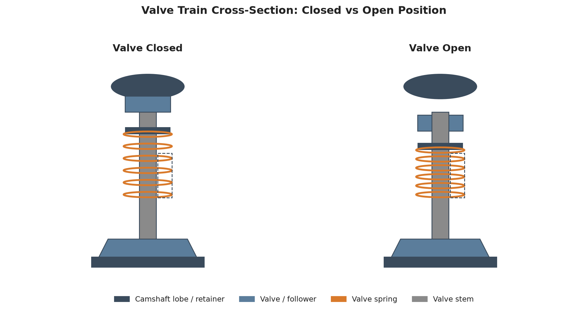
What Is an Engine Valve Spring and How Does It Work?
The Role of the Valve Spring in the Valve Train
Four components decide whether the valve train behaves as designed. First, the camshaft defines the motion. Second, the valve and valve guide define the gas path and sealing surface. Third, the rocker arm or bucket transfers the motion. Finally, the spring makes the motion reversible. If the spring cannot return the valve quickly and completely, the cylinder never sees the camshaft’s designed lift profile.
Three duties follow from that:
- Sealing. The spring’s installed force presses the valve head against the valve seat. Without adequate force, combustion pressure and intake vacuum leak past the seat, and the valve runs hot.
- Follower behaviour. The spring must keep the follower in contact with the cam ramp through the closing flank. Losing contact means the valve lands on the seat with impact, which is where valve bounce and seat recession begin.
- Timing integrity. Valve opening and closing events stay where the camshaft put them only while the spring maintains control. Once control is lost, effective timing drifts with speed.
Compression Spring Fundamentals Behind Valve Springs
Elastic energy, restoring force, and valve follow
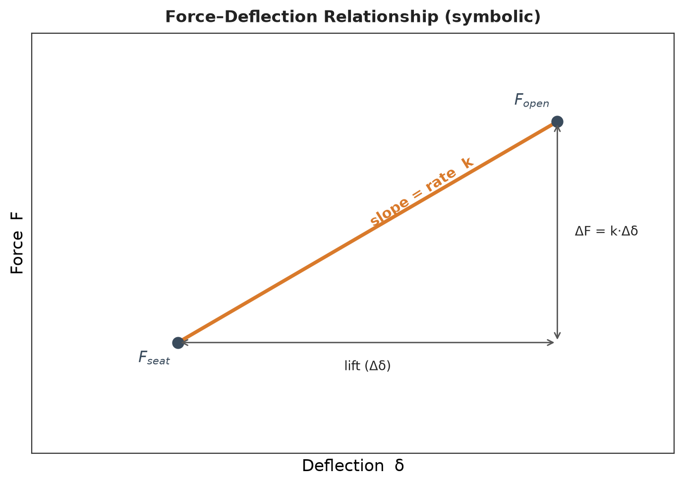
A helical compression spring stores elastic energy when the valve opens and releases it when the valve closes. The relevant engineering quantity is not the energy itself but the force–deflection relationship. Therefore, the spring resists further compression with a force equal to rate multiplied by distance travelled. This linear relationship makes the spring predictable. Because the rate is fixed, the engineer knows the force at every lift position without measuring it.
Why a compression spring, and not another form
A valve spring must generate a force that resists compression and returns to a free position every cycle. Moreover, it must do so inside a housing that is itself a moving, oil-fed, high-temperature environment. A helical compression spring meets all four constraints at once. To begin with, it produces force in axial compression, and it needs no external guide. In addition, it tolerates angular misalignment through its end coils. Finally, it has no mechanism to wear out beyond the material itself.
Why the Valve Spring Is the Most Fatigue-Critical Spring in an Engine
A valve spring accumulates cycles faster than almost any other spring on a vehicle. At sustained engine speed, the spring sees one load cycle per revolution. Over several thousand hours of running, that accumulates to a cycle count measured in tens of millions. Consequently, manufacturers design automotive engine valve springs for a fatigue life well above 5.5 × 10⁷ cycles. The surface condition of the wire then becomes the controlling variable, not a secondary consideration. [D1]
Consequently, wire makers produce dedicated grades for this application. For these grades, surface integrity — not dimensions — is the most tightly specified property.
Valve Spring Material Selection: Why Silicon-Chromium Steel Dominates
The Demands on Valve Spring Material
A valve spring material has to satisfy four constraints simultaneously, and it is the combination that eliminates most candidate steels:
| Constraint | What it does to the material |
|---|---|
| Very high cyclic stress | Requires high fatigue strength and a surface free from crack initiation sites |
| Very high cycle count | Requires the material to resist crack initiation for tens of millions of cycles, not thousands |
| Moderately elevated operating temperature | Requires resistance to loss of load-carrying capacity while hot |
| Stress relaxation | Requires the ability to hold installed load over long periods under sustained stress |
In practice, the fourth point is the one engineers underrate. A spring can pass every static inspection and still fail the engine it is fitted to. The reason is simple: it lost load capacity slowly.
Note on terminology. “Moderately elevated temperature” is the wording used by the applicable wire specifications (ASTM A877/A877M and ASTM A401/A401M) rather than a fixed temperature value. The acceptable temperature window depends on grade, coating, and duty cycle, and you should always confirm it against the specification edition in force.
Oil-Tempered Silicon-Chromium Alloy Steel: The Industry Standard
For automotive engine valve springs, the industry-typical selection is oil-tempered silicon-chromium (Si-Cr) alloy spring wire, supplied to a valve-spring-quality specification.
Specification families at a glance
The relevant specification families are:
| Specification | Title / scope | Why it matters for valve springs |
|---|---|---|
| ASTM A877/A877M | Steel Wire, Chromium-Silicon Alloys, Chrome-Silicon-Vanadium Alloy, Valve Spring Quality | The valve-spring quality specification. Its scope states it is intended for valve springs and other springs requiring high-fatigue properties, and notes the grade is similar to the VD grade referenced in EN 10270-2. [D5] |
| ASTM A401/A401M | Steel Wire, Chromium-Silicon Alloy | The general Si-Cr spring wire specification. Its scope explicitly states it is not intended for high-cycle fatigue applications and directs the user to A877/A877M. It should not be cited as the valve spring specification. [D5] |
| SAE J157 | Oil-Tempered Chromium-Silicon Alloy Steel Wire and Springs | Covers not only the mechanical and chemical requirements of the wire, but also the processing requirements for springs made from it — a useful single reference for wire-plus-process control. [D6] |
| JIS G 3561 | Oil tempered wire for valve springs | The Japanese Industrial Standard is titled specifically for valve springs. Grade designations include SWO-V (carbon), SWOCV-V, and SWOSC-V (silicon-chromium). |
European and national spring wire standards
| Specification | Title / scope | Why it matters for valve springs |
|---|---|---|
| EN 10270-2:2011 | Oil hardened and tempered spring steel wire | Grade families are FD, VD, and TD, with alloy variants such as FDSiCr, VDSiCr, and TDSiCr. VD is the valve spring wire grade, and VD/TD grades are more fatigue-resistant than FD. |
| EN 10270-1 | Patented cold drawn unalloyed spring steel wire | This is the part that defines the SL / SM / SH (static) and DM / DH (dynamic) strength grades. These designations belong to EN 10270-1 and must not be attributed to EN 10270-2. |
| EN 10089:2002 | Hot rolled steels for quenched and tempered springs | Covers the hot-rolled grade 54SiCr6 (material number 1.7102) — relevant when the discussion moves from wire to bar stock. |
| GB/T 18983-2017 | Wire for quenched and tempered springs | The current Chinese national standard, relevant for China-based manufacture and sourcing. |
Common industry designations
Common industry designations in the same composition family include SAE 9254-class chrome-silicon steel, 55CrSi / 55SiCr, and 54SiCr6 (1.7102). Steelmaker datasheets and industry practice use these names widely. Therefore, you should read them as composition-family designations, not as formally declared equivalent grades.
Why the silicon–chromium combination works
Silicon and chromium are not arbitrary additions. Silicon raises the tempering resistance of the steel. As a result, the spring retains its hardness, and its load-carrying capacity, after exposure to operating temperature. Chromium improves hardenability and contributes to the formation of the fine carbides that resist softening. Together, they give the grade family the property that matters most in a valve spring. Consequently, the grade holds a high stress level across tens of millions of cycles without progressively losing load.
“Super-clean” steel and why inclusion content is a fatigue variable
Steelmakers often market valve spring wire as “super-clean” or “super clean steel.” The terminology is a steelmaker’s industry term, not a standardised definition. What it describes is real, however. Non-metallic inclusions are potent fatigue crack initiators. Therefore, reducing inclusion content removes potential failure origins before winding begins. Similarly, controlling inclusion size and distribution does the same. Fewer initiation sites means a longer crack-initiation phase. In fact, that phase dominates the total fatigue life of a spring running at high cycle counts.
Comparison: Silicon-Chromium vs Carbon Steel vs Stainless vs Titanium
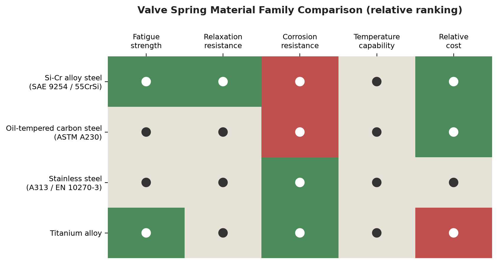
The table below compares material families on the criteria a valve-train engineer actually uses. The ratings are relative and qualitative. Specifically, they indicate ranking against the other families in this table, not measured values.
| Material family (applicable specification) | High-cycle fatigue strength | Stress-relaxation resistance at temperature | Corrosion resistance | Relative material cost | Typical role in valve-spring applications |
|---|---|---|---|---|---|
| Oil-tempered Si-Cr alloy steel — ASTM A877/A877M, SAE J157, JIS G 3561 (SWOSC-V), EN 10270-2 (VD / VDSiCr) | Very high | High | Low without coating | Medium | Industry-typical selection for automotive engine valve springs |
| Oil-tempered carbon valve-spring-quality steel — ASTM A230/A230M | Moderate | Moderate | Low | Low | Light-duty or low-stress springs; not the right choice where high-cycle fatigue governs |
| General Si-Cr spring wire, non-valve-spring grade — ASTM A401/A401M | Not intended for high-cycle fatigue (specification directs to A877/A877M) | Moderate | Low | Medium | General springs at moderately elevated temperatures |
| Stainless spring wire — EN 10270-3; ASTM A313/A313M | Moderate to high | Moderate | High | High | Corrosion-exposed or lightly loaded applications |
| Titanium alloy (e.g. beta-titanium) | Moderate; wear resistance depends on surface treatment | Limited | High | Very high | Motorsport weight reduction, not volume automotive production |
How to read the comparison
The table includes the carbon-steel row to show why the valve-spring-grade row exists. It also includes the non-valve-spring Si-Cr row for the same reason. Both are legitimate spring wire specifications. Even so, neither suits a part that will see tens of millions of load cycles. By contrast, titanium earns its place in the table because it appears frequently in performance discussion. Its position nevertheless reflects a trade: reduced moving mass against very high cost. In addition, the wear surface usually requires treatment. Overall, this titanium comparison reflects general industry practice rather than a standard-based ranking. For environments that exceed what stainless steel or nickel-based superalloys can handle, see our guide to tantalum-tungsten alloy springs.
Stress Relaxation and Why It Matters at Operating Temperature
Stress relaxation means the loss of load, or of usable deflection, while a spring remains under load or cycles repeatedly. Three variables govern it — stress, time, and temperature — and its relationship with all three is exponential. Specifically, the relationship with each variable is exponential. As a result, a modest increase in operating temperature has a disproportionate effect on retained load. [D8]
For a valve spring, the consequence is specific: relaxation reduces the installed force, so seat pressure decays over service life. A spring that you specified correctly at build can still relax in service. Eventually, it reaches a condition where it no longer seals reliably or controls the valve at high speed.
Levers for improving relaxation resistance
Three levers are available, and the interaction between them matters:
- Alloying. Higher alloy content improves relaxation resistance at a given temperature. In addition, this is a direct argument for the Si-Cr family over plain carbon grades. [D8]
- Residual stress control. Forming-induced residual stresses work against relaxation resistance. Therefore, the stress-relief treatment should run at the highest temperature that is practically feasible without damaging the part. [D8]
- Heat setting (hot setting). Heat setting can eliminate a large proportion of first-stage relaxation and/or establish a favourable residual stress pattern. Moreover, in compression springs it can produce a measurable growth in free length — typically no more than 1–2 %. For that reason, we dimension heat-set springs after the operation, not before it. [D9]
A trade-off that engineers frequently misstate. Shot peening is excellent for fatigue performance but is detrimental to stress relaxation resistance. [D10] Any specification that calls for shot peening on a valve spring must therefore pair it with an appropriate heat-setting or stress-relief step. Shot peening alone is not a universal improvement.
Material Selection Checklist for Engineers
- Confirm the governing load case: is the spring fatigue-limited, relaxation-limited, or both?
- Confirm the operating temperature band and communicate it explicitly, because relaxation is exponentially sensitive to temperature.
- Specify the wire by valve-spring-quality specification (ASTM A877/A877M, SAE J157, JIS G 3561, or EN 10270-2 VD/VDSiCr). Never specify a general spring wire grade.
- Specify surface quality requirements — permissible surface defect depth and the inspection method — since surface condition governs fatigue initiation.
- Specify whether shot peening is required, and confirm that the process sequence includes a compatible heat-setting or stress-relief step.
- Specify corrosion protection appropriate to the installation, and confirm that the coating process does not impair fatigue performance.
- Require the wire supplier’s certification and traceability. Then confirm the grade is the valve-spring quality grade, not a general Si-Cr grade of similar nominal composition.
Valve Spring Failure Modes: Causes, Symptoms and Prevention
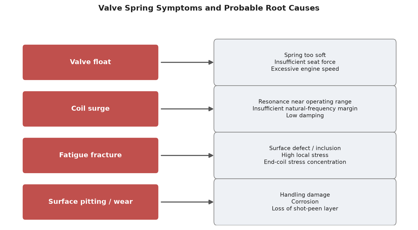
Symptom-to-Cause Map
| Observed symptom | Likely root cause family | First diagnostic step |
|---|---|---|
| Power loss at high engine speed only | Valve float — spring force insufficient to follow the cam at that speed | Compare the spring’s natural frequency against cam excitation frequency in the speed range |
| Misfire or rough running that appears above a specific RPM | Valve float or valve bounce; possible loss of follower contact | Inspect the cam ramp and follower for contact marks; verify installed force |
| Audible rattle or ticking from the valve cover | Coil surge, valve bounce, or lost follower contact | Check for spring resonance and end-coil seating condition |
| Broken spring with no other visible damage | Fatigue fracture initiating at a surface defect or at a coil transition | Examine the fracture origin under magnification; measure surface defect depth |
| Progressive loss of performance in service with intact springs | Stress relaxation reducing seat pressure | Measure installed force against the original specification |
| Corrosion pitting on spring surface | Inadequate coating for the environment; pitting acts as a crack initiator | Review corrosion protection specification against actual operating environment |
Valve Float: When the Spring Loses Control
Valve float happens when the inertial force required to decelerate the valve and follower exceeds the force the spring can supply. Above that speed, the follower separates from the cam. Valve events then lose their designed timing, and the valve may contact the piston.
The relationship is explicit, and it is worth stating as an equation of tendency rather than a number:
Inertial demand grows with the square of engine speed, while spring force stays essentially fixed by design. Doubling speed approximately quadruples the inertial load the spring must overcome.
That is why valve float is a high-speed failure mode. It appears as a threshold phenomenon: the engine behaves normally up to a speed, then abruptly stops behaving normally. Three variables move the threshold: valve train reciprocating mass, cam acceleration, and spring force. First, lower mass helps. Second, aggressive profiles raise the demand. Higher spring force raises the threshold — but see the trade-off below.
Coil Surge: Resonance Between the Valve and the Spring
A compression spring is not a rigid body. It is a distributed mass-spring system, and it therefore has its own natural frequencies. Meanwhile, the camshaft supplies a periodic excitation. The camshaft imposes an excitation frequency. When that frequency approaches one of the spring’s natural frequencies, the spring enters coil surge. Waves of compression and extension then travel along the coil. The end coils and centre coils no longer move in phase. As a result, the force delivered to the valve becomes erratic.
Surge is harmful because it does not simply reduce force. Instead, it makes force unpredictable at exactly the speed where control matters most. Published valve spring research shows that end coil geometry affects the natural frequency of an automotive engine valve spring. Therefore, the end coil design is a functional parameter, not a manufacturing detail. [D18] Moreover, surge amplitude prediction requires a model that accounts for both a varying natural frequency and a varying damping ratio. Treating the spring as a constant-frequency element is not enough. [D19]
Common countermeasures include variable pitch, nested or dual springs, and friction damping between spring and retainer. All three work the same way. They disrupt the distributed mass-spring system that allows a clean standing wave to form.
Fatigue Fracture: Where Cracks Start
Valve spring fatigue failure is almost always an initiation-controlled process. The crack starts at a stress concentration. Thus, the location of that concentration is the key diagnostic evidence.
Documented crack initiation locations
Research documents two validated initiation locations:
- The inside surface of the spring. Research on surface flaws in oil-tempered wire for automotive engine valve springs identifies the spring’s inside surface as the principal crack location. It is the surface in tension during winding. It is also the surface least accessible to inspection and finishing. [D13]
- The transition from the bearing (end) coil to the first active coil. Failure analysis of helical compression springs places fracture at exactly this transition. There, the coil geometry changes and local stress rises. [D14]
What the case study shows
A case study of a high-strength motorcycle valve spring adds an important nuance. The spring failed in a factory fatigue test after 6.21 × 10⁶ cycles, against a required life of 2.30 × 10⁷ cycles. Notably, the crack initiated at the outside surface. The crack origin zone still retained approximately −400 MPa of residual compressive stress. Inspectors detected no conventional defect at the initiation site. [D15]
The lesson from that case is not that a specific process is inadequate. Instead, it is that residual compressive stress is itself a fatigue variable that can relax progressively during cycling. As a result, a spring whose surface treatment was correct at manufacture can still initiate a crack later. That happens when the compressive layer degrades faster than the crack initiation threshold can tolerate. Increasing shot peening intensity does not automatically extend life. The residual stress field has to remain effective for the required cycle count. [D11]
Surface Engineering: Shot Peening, End Grinding and Nitriding
Shot peening: how it works and how to control it
Shot peening is a line-of-sight cold working process that fires hard media at the spring surface. It generates a beneficial residual compressive stress field beneath the surface layer. Because fatigue cracks initiate where tension exists, a compressive layer at the surface suppresses initiation. It also pushes the initiation site below the compressive zone. [D7][D11]
Controlling the process requires three specification elements: shot size, shot type, and Almen arc height. Arc height is the controlled variable, and the process specification sets it at 100 % coverage (saturation). Technicians measure it on Almen strips. Type A (76 × 19 × 1.30 mm) covers standard intensities, and Type N (76 × 19 × 0.80 mm) covers lower intensities. These are test specimen dimensions, not product dimensions. Media are typically high-hardness conditioned cut wire or cast steel shot. Glass bead serves non-ferrous springs. Steel shot sizes start at the S070 designation (nominal diameter 0.18 mm). Operators must match shot size to the wire being processed. Shot that is too large relative to the wire deforms the spring. As a result, it can degrade fatigue performance rather than improve it. [D7]
Institutions specialising in spring shot peening have accumulated several decades of application experience in this process. Therefore, you should always write the requirement as a process specification, not as a “peened / not peened” checkbox. [D7]
End grinding and edge rounding
Manufacturers grind compression springs at the ends so that they stand square and transmit load uniformly into the seat. Grinding exposes the end of the wire section. The sharp transition between the ground end and the first active coil is a documented fracture location. [D14] Edge rounding and controlled grinding practice reduce that local stress concentration. In practice, this engineering measure costs little and removes a known crack initiation site.
Nitriding and phosphate coating
Nitriding raises surface hardness, wear resistance, fatigue strength, and corrosion resistance in ferrous alloys generally. In addition, industry applies it as a general surface engineering measure. You should not treat it as a standard valve spring process without a specification requirement. Specifically, such a requirement must define the case depth and its effect on the substrate. By contrast, phosphate coatings serve a different purpose — corrosion protection during storage and service. However, the coating process must never reduce the fatigue performance it protects.
How to Prevent Premature Failure
Design side 1. Verify the spring’s natural frequency against the camshaft excitation frequency across the full speed range, not only at rated speed. 2. Confirm that the spring retains adequate force at maximum lift, not only at installed height. 3. Avoid the over-soft spring failure mode; however, also recognise the cost of an over-stiff one (see Seat Pressure and Open Pressure). 4. Define end coil geometry as a functional specification item.
Material side 5. Specify valve-spring-quality wire (ASTM A877/A877M, SAE J157, JIS G 3561, or EN 10270-2 VD/VDSiCr) — not a general Si-Cr wire of similar nominal composition. 6. Specify permissible surface defect depth and require verification by an appropriate inspection method. 7. Require inclusion-content control from the wire supplier.
Process side 8. Specify shot peening as a process specification. Include shot size, shot type, Almen arc height at 100 % coverage, and Almen strip type. 9. Match shot size to wire size to avoid deformation. 10. Pair shot peening with heat setting or stress relief, since peening alone is detrimental to relaxation resistance. 11. Control end grinding and edge rounding quality.
Assembly side 12. Verify installed height and installed force at assembly, because installed force is what the engine actually sees. 13. Protect the spring surface during handling and installation — a handling scratch is a potential crack initiation site. 14. Confirm seat and retainer condition, since a worn seat changes the effective installed height.
The Engineering Logic Behind Valve Spring Parameters
This section explains how valve spring parameters relate to each other and to engine behaviour. It uses symbols and relationships, not fixed values. The correct value of every parameter below depends on a specific cylinder head, cam profile, and duty cycle.
Spring Rate and the Effect of Active Coils
Spring rate (k) is the force required to compress the spring by unit distance. For a helical compression spring it follows the standard relationship:
$$k = \frac{G \cdot d^4}{8 \cdot D^3 \cdot n_a}$$
Here G is the shear modulus of the material, and d is the wire diameter. Also, D is the mean coil diameter and n_a is the number of active coils.
Three conclusions follow directly from the exponents, and they explain most design conversations about valve springs:
- Wire diameter dominates. Rate varies with the fourth power of wire diameter. As a result, a small change in wire size produces a disproportionate change in rate.
- Coil diameter is nearly as influential. Rate falls with the third power of mean coil diameter. A larger-diameter spring of the same wire is much softer.
- Active coils tune the rate linearly. Rate is inversely proportional to the number of active coils. That is why spring calculations use “active coil count” rather than “total coil count”. End coils that are closed and ground do not contribute to deflection the same way active coils do.
There is also a non-linearity that matters at speed. As a spring compresses, the number of effectively active coils does not remain exactly constant. Consequently, a real valve spring is not a perfectly linear element. Valve train dynamic models capture this. They represent the spring as a multi-segment mass-elastic system rather than a single spring constant. [D17]
Free Length vs Installed Height vs Solid Height
Engineers frequently use these three terms interchangeably in conversation and then confuse them in specification. They are distinct:
| Term | Definition | Why it matters |
|---|---|---|
| Free length | The spring’s axial length in the unloaded condition | The starting point for every other dimensional calculation |
| Installed height | The axial length the spring occupies when the valve is closed and the retainer is seated | Sets the installed spring force — the force that seals the valve |
| Solid height | The axial length when all coils are in contact | Defines the mechanical limit; exceeding it damages the spring |
The relationship that engineers most often need to restate is this: installed height, not free length, determines seat pressure. Two springs with the same free length but different rates will produce different installed force at the same installed height. Conversely, any change to a component in the valve train stack changes installed height. Valve, retainer, seat, and cylinder head work all count. That changes installed force, even if you never touch the spring itself.
Seat Pressure and Open Pressure: What Each One Governs
Seat pressure is the force the spring exerts with the valve closed. It governs two things: sealing of the valve against its seat, and valve train stability at low speed. At low speed, gas forces are most likely to disturb the valve.
Open pressure is the force the spring exerts at maximum valve lift. It governs the spring’s ability to keep the follower on the cam through the aggressive part of the profile. It therefore sets the upper limit of controllable engine speed.
A single relationship links the two:
$$F_{\text{open}} – F_{\text{seat}} = k \times \text{lift}$$
Therefore, the spring rate and the cam lift fully determine the difference between open and seat force. Therefore, raising engine speed capability is not simply a matter of “a stronger spring”. The available lever is rate, and rate affects both ends of the curve at once.
Why “stiffer” is not automatically better
The two-sided trade-off. A spring that is too soft produces valve float at high speed, because it cannot supply enough force to control the follower. A spring that is too stiff increases valvetrain friction and causes power loss, and it raises the camshaft driving torque required from the engine. Both directions carry a real cost, and published heavy-duty diesel valve train studies treat this balance explicitly rather than treating “stiffer” as strictly better. [D16]
DIN EN 13906-1:2013 specifies compression spring calculation and design. It includes the fatigue strength diagrams that engineers use to assess a spring’s cyclic stress against its material. That standard is the correct reference when the question is “will this design survive the required cycle count.” [D20]
Natural Frequency, Valve Float and Critical Engine Speed
The designer must keep a valve spring’s natural frequency away from the excitation frequency that the camshaft imposes. The scaling relationship is:
$$f_n \propto \frac{d}{D^2 \cdot n_a} \sqrt{\frac{G}{\rho}}$$
Here d is wire diameter, D is mean coil diameter, and n_a is the number of active coils. Also, G is shear modulus and ρ is material density.
Consequently, two practical consequences follow:
- Light, stiff, short springs have higher natural frequencies. This is the design logic behind compact, high-rate springs in high-revving engines. It also explains weight-optimised spring forms in performance applications.
- The spring is a distributed system, not a point mass. Modelling it as a single-degree-of-freedom element misses the internal dynamics that produce surge. For this reason, valve spring research models the varying natural frequency and the varying damping ratio. No other approach predicts surge amplitude accurately. [D19]
Confirming a spring’s survivability against cyclic stress is a design calculation. Confirming that a supplied spring actually meets it is a test question. Therefore, three fatigue test methods apply. DIN 50100 covers load-controlled fatigue testing, and it applies to specimens and components. By contrast, ISO 1099 covers axial force-controlled fatigue testing, and it applies only to specimens. Finally, ASTM E466 covers force-controlled constant-amplitude axial fatigue testing of metallic materials, and it explicitly excludes components or parts. For valve springs as finished components, this distinction matters when you write a verification requirement. [D21]
Why We Don’t Publish Fixed Dimensions
A natural question from a buyer or from a practising engineer is: give me the numbers. Here is the honest engineering answer.
Wire diameter, coil count, free length, and spring diameter are the four parameters that define a valve spring’s behaviour. In fact, published valve train dynamics work uses exactly this parameter set. [D17] Moreover, the application determines every one of those parameters. Specifically, these include the cylinder head envelope, the cam profile, the valve mass, and the forces required at installed and open positions. They also include the operating temperature and the required cycle count. In other words, they are customer inputs derived from a specific engine, not a manufacturer’s standard part.
What a spring manufacturer actually contributes is not a number but the ability to achieve the right number repeatedly:
- Tolerance control — holding the specified rate and force window across production, not just on a prototype
- Process consistency — identical heat treatment, peening, and heat-setting outcomes from batch to batch
- Design reverse-engineering — turning a sample, a photograph, or a set of measured points into a manufacturable, calculated drawing
- Material and process specification discipline — specifying valve-spring-quality wire and controlled surface engineering rather than accepting “equivalent” substitutes
Therefore, we write our published material at the level of principle, specification, and process. In addition, we deliver the dimensioned drawing in the quotation, against your application.
Custom Valve Spring Sourcing: What to Prepare and How We Work
The RFQ Checklist: Information Engineers Should Provide
In practice, the fastest route to an accurate custom valve spring quotation is a complete requirement set. If you are preparing a request for quotation, the following information removes almost all of the back-and-forth:
How to structure your request
Geometry and force (the four governing parameters) 1. Wire diameter required (or the free choice of wire size) 2. Outer diameter, inner diameter, or the available installation envelope 3. Free length and installed height — or the required installed force 4. Required spring rate, or the required force at two defined positions 5. Maximum valve lift and the maximum compression the spring will see 6. Coil count constraints, if the installation imposes any
Mechanical duty 7. Required force at installed height (seat) and at maximum lift (open) 8. Expected maximum engine speed 9. Required fatigue life or expected service cycle count 10. Valve train reciprocating mass, if available — it determines inertial demand
Material and environment 11. Required material grade or specification (we assume valve-spring-quality wire unless you specify otherwise) 12. Operating temperature range, including any transient peaks 13. Corrosion exposure and required coating 14. Any mandatory standard the spring must meet
Surface engineering 15. Shot peening requirement, if specified by your own design 16. Any additional surface treatment requirement
Commercial 17. Prototype quantity and production quantity 18. Required delivery date and any milestone constraints 19. Inspection and documentation requirements (material certificates, dimensional reports, first-article inspection) 20. Any customer-specific quality or traceability requirements
If you have some of the geometry but not all of it — or none at all — do not delay the enquiry. A sample and a description of the application is enough to start.
DFM Reverse Engineering: From Photo or Sample to Drawing
Not every enquiry arrives as a dimensioned drawing. Rebuild shops, replacement-part specialists, and importers frequently hold a physical spring. In some cases, they hold only a photograph of the original part. The workflow we use for that situation is:
- Receive the artefact. A physical sample, or photographs with a measurement reference in frame.
- Measure the governing parameters. These are wire diameter, coil diameters, free length, coil count, end configuration, and end grinding condition. Together they establish the four parameters that define behaviour. [D17]
- Verify and cross-check. We reconcile the measured geometry against the application duty the customer describes. That way, the drawing reflects the load case the spring must survive, not merely the worn sample in hand.
- Model and calculate. We calculate rate, stress at installed and open conditions, and natural frequency behaviour. We then check the design against the required cycle count, using the design approach of DIN EN 13906-1. [D20]
- Produce a manufacturable drawing. The drawing defines tolerances, material specification, surface engineering, and inspection requirements.
- Quote. We issue the quotation against that drawing, so both parties work from the same specification.
The purpose of reverse engineering is not merely to copy an existing part. Instead, it is to convert an unknown part into a specified one. As a result, the replacement then performs the function of the original, including the material and surface quality. Indeed, the original may have had that quality, and a copy might not.
Manufacturing Capability Indicators Buyers Should Verify
When you evaluate a valve spring supplier, these indicators predict whether production parts will match the approved sample.
Capability checklist
| Indicator | What to ask for |
|---|---|
| Quality management certification | Documented certification to ISO 9001 and IATF 16949. Hengsheng Spring holds both, and the certifications are stated publicly on our website. |
| Independent verification | Evidence of inspection and testing carried out by an independent body such as SGS. |
| Material specification discipline | Confirmation that valve-spring-quality wire (ASTM A877/A877M-class, SAE J157, JIS G 3561, or EN 10270-2 VD/VDSiCr) is used rather than a general-purpose Si-Cr grade. |
| Surface engineering control | A written shot peening process specification covering shot size, shot type, and Almen arc height at 100 % coverage, with the Almen strip type stated. |
| Defect control | The permissible surface defect depth, the inspection method used to verify it, and whether it is a buyer–seller agreed figure or a standard-specified limit. |
| Batch consistency evidence | Rate and force measurement data across production batches, not only prototype data. |
| Traceability | Material certificates and lot traceability from wire to finished spring. |
On surface defect limits specifically
In practice, the applicable wire specifications do not all take the same approach. DIN EN 10270-2 specifies a permissible surface defect depth of less than 0.5–1 % of wire diameter for wire in the 0.5–10 mm range, while JIS G 3561 and KS D 3580 specify less than 0.5 % for wire in the 0.5–8 mm range. ASTM A877/A877M leaves the permissible defect depth to agreement between manufacturer and purchaser. [D3] Where the defect limit is a matter of agreement, the purchasing specification should state it explicitly. In addition, eddy current in-line inspection of wire can detect surface defects down to a depth on the order of 40 µm. [D4]
Process Flow for a Custom Valve Spring
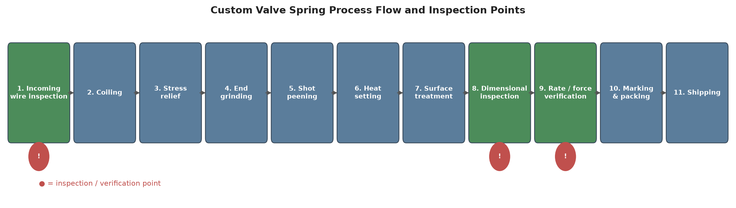
From a confirmed specification, a custom valve spring passes through the following stages. Note that each stage has an inspection point, and the sequence matters, because you cannot reorder several of these operations without changing the result:
- Wire selection and incoming inspection — valve-spring-quality wire, verified against the material certificate
- Coiling — cold winding to the calculated geometry
- Stress relief — residual stress control after forming
- End grinding — end faces ground square to transmit load evenly
- Edge rounding — reduction of local stress concentration at the ground ends
- Shot peening — process-specified, with Almen arc height controlled at 100 % coverage
- Heat setting — stabilisation of free length and reduction of first-stage relaxation (performed before final dimensional verification, since heat setting can change free length)
- Surface finishing — coating for corrosion protection, selected so as not to impair fatigue performance
- Dimensional and force inspection — rate, installed force, free length, and squareness against drawing
- Surface defect inspection and final sorting — removal of any spring with a surface condition that could initiate a fatigue crack
- Documentation — inspection records and material traceability released with the shipment
Start Your Valve Spring Project
If you are sourcing a cylinder head valve spring — for an engine rebuild programme, a replacement-part range, a performance application, or a new design — the most useful first step is to send us what you have:
- A dimensioned drawing, or
- A physical sample, or
- Photographs of the original spring with a measurement reference in frame, plus a description of the engine and duty
We will review the requirement, carry out the design calculation, and come back with a specification and a quotation. Moreover, where the original part is unknown, we will reverse-engineer it into a fully specified drawing before quoting.
Request a custom valve spring quotation →
Valve Springs Across Engine Types and Applications
Gasoline vs Diesel Engines: Different Valve Train Demands
Gasoline and diesel engines impose different duty on the valve spring, and the differences are qualitative but decisive:
- Speed range. First, gasoline engines of the performance-oriented type operate over a wider and higher speed range, which raises the excitation frequency the spring must tolerate and pushes the natural frequency requirement upward.
- Combustion pressure and gas load. Notably, diesel combustion pressures are substantially higher, and the gas forces acting on the valve add to the spring’s workload at the seat.
- Thermal load. Similarly, diesel exhaust-side temperatures are higher and more sustained, which places greater weight on the material’s relaxation resistance.
- Valve train mass. Moreover, heavy-duty diesel valve trains commonly use heavier components, raising the inertial demand at any given speed.
Published work on heavy-duty diesel valve trains models the valve spring as a multi-segment mass-elastic system precisely because these effects are not negligible — and it identifies the same two-sided trade-off: a spring that is too soft floats at high speed, while one that is too stiff costs friction and power. [D16] In addition, the study treats valve-bounce behaviour, loss of cam–follower contact, and crosshead tilt as coupled dynamic outcomes rather than isolated spring problems. [D16]
Naturally Aspirated vs Turbocharged
In practice, boost changes the pressure environment on both sides of the valve, and the exhaust side is usually the more demanding:
- Higher cylinder pressure at the seat. First, increased charge pressure acts on the valve head and adds to the force the spring must hold against during the closed period.
- Higher exhaust gas temperature. Second, turbocharged exhaust-side valves and their springs operate in a hotter environment, which shifts the balance toward relaxation resistance and away from pure fatigue strength.
- Higher thermal transients. Third, boost onset and shutdown produce temperature swings, and thermal cycling interacts with the residual stress field in the spring surface.
The practical consequence is decisive. In practice, a spring specified for a naturally aspirated version of an engine family will not automatically suit its turbocharged derivative, even where the cylinder head casting is shared.
Passenger Vehicles vs Performance and Racing Engines
In practice, performance applications raise the required seat pressure and natural frequency, because the engine must control the valve at speeds where a production spring would float. However, raising the required force has consequences that racing engineers manage deliberately:
- Higher force means higher camshaft drive torque, which is power the engine pays for continuously. [D16]
- Higher stress accelerates relaxation, so the spring must handle both the stress level and the temperature, not only the force. Note that this applies to the whole valve train, not the spring alone.
- Reduced-moving-mass design becomes worthwhile, but weight reduction usually comes with a material or surface-treatment cost that you must justify per application.
Case Context: Sourcing Valve Springs for Light Commercial Pickup Valve Train Rebuilds
In practice, a recurring pattern in replacement-part sourcing is the light commercial pickup engine that is rebuilt or maintained in regions where factory parts are expensive or slow to obtain. A recent enquiry we handled came from a South American engine rebuilding workshop. The workshop needed cylinder head valve springs for a light commercial pickup engine, and it had measured the original spring rather than holding a factory drawing.
This is a common and workable starting point, and it defines the practical requirements for a supplier:
- Reverse engineering from a measured sample — turning measurements into a drawing, then verifying the geometry against the required load case (see DFM Reverse Engineering)
- Surface and material equivalence — using valve-spring-quality wire and controlled surface engineering, so the rebuild avoids the same failure
- Repeatable production at moderate volume — rebuild programmes need consistent parts over a period of years, not a single batch
- Clear documentation — so the workshop can verify installed force at assembly
Matching Springs to Application: A Decision Framework
- Define the duty first. Maximum engine speed, cam profile, valve train mass, and required cycle count. Geometry follows from these.
- Establish the force requirement at both ends. Installed force for sealing and stability; open force for control at maximum speed.
- Check the speed–frequency relationship. Confirm the natural frequency sits clear of the excitation range, and treat end coil geometry as a functional parameter.
- Set the thermal and relaxation requirement. If the application runs hot or holds load for long periods, relaxation resistance governs material and process choice.
- Specify the material by the correct specification. Valve-spring-quality wire, named specification, with surface defect limits stated.
- Specify the surface engineering as a process. Shot peening controlled by Almen arc height at 100 % coverage, matched shot size, plus a compatible heat-setting step.
- Require verification. Rate and force measurement, surface inspection, and material certification.
FAQ: Engine Valve Spring Questions Engineers Ask Most
What material are engine valve springs made of?
In practice, manufacturers make automotive engine valve springs from oil-tempered silicon-chromium alloy spring wire produced to a valve-spring-quality specification — ASTM A877/A877M, SAE J157, JIS G 3561 (grade SWOSC-V), or EN 10270-2 grade VD/VDSiCr. The silicon and chromium content provides tempering resistance and fatigue strength at moderately elevated operating temperatures. By contrast, engineers specify carbon valve-spring-quality steel (ASTM A230/A230M) for lighter duty service. [D5]
Why do valve springs fail?
In practice, valve springs fail predominantly by fatigue crack initiation at a surface stress concentration, not by gross overload. Documented initiation sites include the spring’s inside surface and the transition from the bearing coil to the first active coil. In addition, valve spring research reports surface defects, corrosion pits, non-metallic inclusions, decarburisation, and insufficient or degraded residual compressive stress as contributing factors. [D12][D13][D14][D15]
What causes valve float at high RPM?
Specifically, valve float occurs when the inertial force needed to decelerate the valve train exceeds the force the spring can supply, so the follower separates from the cam and valve events lose their designed timing. The inertial demand rises with the square of engine speed, while the spring’s force stays fixed by design. That is why float appears as an abrupt threshold rather than a gradual loss. [D16]
What is coil surge and why is it harmful?
In essence, a valve spring is a distributed mass-spring system with its own natural frequencies. When camshaft excitation approaches one of them, compression waves travel along the coil, adjacent coils move out of phase, and the force delivered to the valve becomes erratic — at precisely the speeds where control matters most. Therefore, end coil geometry affects the natural frequency. Countermeasures include variable pitch, nested springs, and damping. [D18][D19]
What is the difference between seat pressure and open pressure?
First, seat pressure is the spring force with the valve closed; it governs sealing and low-speed stability. Second, open pressure is the force at maximum valve lift; it governs the spring’s ability to keep the follower on the cam, and therefore the controllable engine speed. Therefore, their difference equals spring rate multiplied by valve lift — so one lever, the rate, sets both. [D20]
How is installed height different from free length?
First, free length is the spring’s unloaded axial length. Second, installed height is the axial length it occupies with the valve closed and the retainer seated. Consequently, installed height — not free length — sets the installed force. Any change to the valve train stack that alters installed height therefore changes seat pressure, even if the spring itself stays the same.
Do I need single, double, or beehive valve springs?
In short, these are three different engineering approaches rather than three quality levels. For example, a nested or dual spring combines two springs acting in parallel to raise total force within a limited envelope. Similarly, beehive springs change cross-section and mass distribution along the spring to alter the mass-spring behaviour. Therefore, the correct choice follows from the duty: required force, speed range, valve train mass, and available space.
How long do valve springs last?
No universal service interval exists, but the design target indicates the order of magnitude. Manufacturers typically design automotive engine valve springs for a fatigue life greater than 5.5 × 10⁷ cycles. In practice, actual life depends on surface condition, operating temperature, stress level, and how much load the spring loses to stress relaxation over time. [D1]
Can valve springs be reused after an engine rebuild?
In short, the spring supplier or the engine manufacturer’s service specification for that application should decide reuse — not appearance. Therefore, the practical verification is measurement: compare the spring’s installed force against the original specification, because stress relaxation reduces force without producing any visible defect. Finally, assess springs that have run in a high-temperature, high-cycle environment on measured force rather than visual condition.
How do I request a quote for custom valve springs?
Send whatever level of information you have. Of course, a dimensioned drawing is ideal. If you do not have one, provide a physical sample, or photographs of the original spring with a measurement reference, plus the engine and duty description. In that case, suppliers offering design reverse-engineering will measure the part, calculate the governing parameters, produce a manufacturable drawing, and quote against it.
Conclusion
Engine valve spring selection comes down to a short chain of engineering decisions. First, the duty — speed range, cam profile, valve train mass, and cycle count — defines the force requirement. Second, the force requirement, combined with the operating temperature and the expected relaxation over service life, defines the material. For automotive valve service, that material is oil-tempered silicon-chromium valve-spring-quality wire. Third, the surface condition of that wire matters, and so does the surface engineering applied to the finished spring. Together they define whether the part reaches its required cycle count. Finally, the manufacturing process defines whether every spring in the batch behaves like the approved sample.
Hengsheng Spring has manufactured springs for over two decades, holds ISO 9001 and IATF 16949 certification, and has undergone independent inspection by SGS. In addition, we work with engineers and procurement teams to specify valve springs from a drawing, a sample, or a photograph — including full reverse engineering where the original specification is unknown.
Send us your drawing, sample, or photos and request a quotation →